87/112
EQUIPMENT
GENERAL INTRODUCTION
(As far as possible) use electric appliances with double insulation or with three
conductors (Neutral-Live wire-Ground).
ELECTRONIC
Wire runs are available to complete the boat equipment.
Do not install electronic instruments or repeaters less than 1,50 m away from the radio
loudspeakers.
ADVICE: For further information refer to the appliance instructions.
LEAD LINES
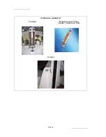
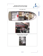
The loch and depth sounder transducers are located in the engine compartment, to port. Keep
the log sensor cowl close to the instrument so as to be able to intervene in complete safety.
Do not store material on top of the sensors.
AUTO PILOT
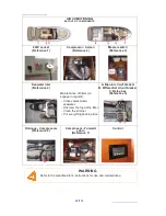
The pilot consists of several elements listed as follows:
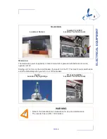
- Repeater, located under the wheel house.
- Compass and Calculator drivers in the cockpit locker.
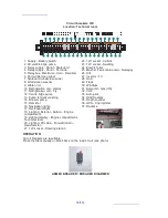
- To supply power to all elements switch on the "Navigation" circuit breaker on the electrical
panel.
- For use and maintenance of the material consult the manufacturer instructions
MAINTENANCE
Clean the transducer probe during each dry dock and the log sensor regularly. Read the
instructions for maintenance recommendations.
Refer to chapter 12 "Launching" for the precautions to be taken concerning the sensors during
hoisting.
Clean the repeater dials with freshwater. Refer to the instructions before using any other
produce. The use of alcohol must be avoided.
ADVICE - RECOMMENDATION
- For best results, remove any metal compass.
- Do not store material close to the calculator and electrical connections.
ADVICE - RECOMMENDATION
- Place the protective covers on the repeaters when unused for long periods.
- When sailing store the protective covers inside the boat to avoid losing them.
- The various repeater displays are back-lit.
- The onboard radio is fitted with two outside speakers.
- When mooring be careful to adjust the sound so as not to disturb your neighbours.
8
E
L
E
C
T
R
IC
A
L
E
Q
U
IP
M
E
N
T
Summary of Contents for 350
Page 1: ...PRESTIGE 350 OWNER S MANUAL S PORTS ET LOISIRS 123682 Index E ...
Page 2: ......
Page 4: ......
Page 7: ...3 112 HISTORY OF UPDATES Index A 02 2011 Index B 10 2011 Index C 11 2012 Index D 03 2013 ...
Page 8: ......
Page 10: ......
Page 11: ...7 112 SPECIFICATIONS AND WARRANTY TECHNICAL SPECIFICATIONS DESIGN CATEGORY YOUR BOAT 1 ...
Page 16: ......
Page 21: ...17 112 POSITION OF GAS BOTTLE 2 SAFETY ...
Page 35: ...31 112 HULL MAINTENANCE OF THE HULL LIFTING 3 ...
Page 38: ......
Page 49: ...45 112 STEERING SYSTEM STEERING GEAR 5 ...
Page 51: ...47 112 INTERIOR INTRODUCTION INTERIOR MAINTENANCE MAINTENANCE OF FABRICS INTERIOR EQUIPMENT 6 ...
Page 52: ...48 112 INTRODUCTION Saloon Cabins ...
Page 55: ...51 112 INTERIOR EQUIPMENT Sink Sliding hatch Must be secured while sailing 6 INTERIOR ...
Page 70: ......
Page 80: ...76 112 HYDRAULIC GANGWAY Location Maximum load 170kg Length Folded out 2 3m Control ...
Page 93: ...89 112 ENGINE GENERAL INFORMATION ENGINE INSTALLATION 9 ...
Page 105: ...101 112 LAUNCHING LAUNCHING RECOMMENDATIONS 10 ...
Page 106: ...102 112 POSITION OF HOISTING CRADLE AND STRAPS Note Measurements are expressed in mm ...
Page 108: ...104 112 Note Measurements are expressed in mm Vue avant 2950 389 389 3728 2600 2950 ...
Page 111: ...107 112 WINTER STORAGE LAYING UP PROTECTION AND MAINTENANCE 11 ...
Page 114: ......
Page 116: ......

