


30/112
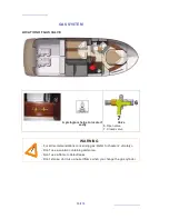
MANUAL BILGE PUMP
The manual bilge pump is in the cockpit.
The control arm of the pump shall be kept accessible whatever the circumstances. It is located
in the cockpit locker.
INSTRUCTIONS IN THE EVENT OF STEERING GEAR FAILURE
On a twin-engined vessel the emergency tiller system works on the difference in drive between
the port and starboard engines (difference in throttle and/or forward/aft).
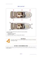
WARNING
- The bilge pump system is not designed to provide buoyancy to the boat in
case of damage.
- The bilge pump system is designed to drive out the water being either sea
spray or leaks but absolutely not the water coming through a hole in the hull,
this hole being the result of a damage.
- Do not let the pumps run while dry, this may cause them damage.
- The water in the bilge shall be kept at its minimum.
- Check the functioning of each bilge pump regularly.
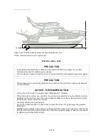
SAFETY PRECAUTIONS
- Clean off debris which could block the pump intake points or strainers. If the watertight
partitions which seal off the fore and aft points are fitted with valves they must be closed
at all times and only opened to drain water into the main bilge.
Summary of Contents for 350
Page 1: ...PRESTIGE 350 OWNER S MANUAL S PORTS ET LOISIRS 123682 Index E ...
Page 2: ......
Page 4: ......
Page 7: ...3 112 HISTORY OF UPDATES Index A 02 2011 Index B 10 2011 Index C 11 2012 Index D 03 2013 ...
Page 8: ......
Page 10: ......
Page 11: ...7 112 SPECIFICATIONS AND WARRANTY TECHNICAL SPECIFICATIONS DESIGN CATEGORY YOUR BOAT 1 ...
Page 16: ......
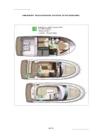
Page 21: ...17 112 POSITION OF GAS BOTTLE 2 SAFETY ...
Page 35: ...31 112 HULL MAINTENANCE OF THE HULL LIFTING 3 ...
Page 38: ......
Page 49: ...45 112 STEERING SYSTEM STEERING GEAR 5 ...
Page 51: ...47 112 INTERIOR INTRODUCTION INTERIOR MAINTENANCE MAINTENANCE OF FABRICS INTERIOR EQUIPMENT 6 ...
Page 52: ...48 112 INTRODUCTION Saloon Cabins ...
Page 55: ...51 112 INTERIOR EQUIPMENT Sink Sliding hatch Must be secured while sailing 6 INTERIOR ...
Page 70: ......
Page 80: ...76 112 HYDRAULIC GANGWAY Location Maximum load 170kg Length Folded out 2 3m Control ...
Page 93: ...89 112 ENGINE GENERAL INFORMATION ENGINE INSTALLATION 9 ...
Page 105: ...101 112 LAUNCHING LAUNCHING RECOMMENDATIONS 10 ...
Page 106: ...102 112 POSITION OF HOISTING CRADLE AND STRAPS Note Measurements are expressed in mm ...
Page 108: ...104 112 Note Measurements are expressed in mm Vue avant 2950 389 389 3728 2600 2950 ...
Page 111: ...107 112 WINTER STORAGE LAYING UP PROTECTION AND MAINTENANCE 11 ...
Page 114: ......
Page 116: ......