12
13
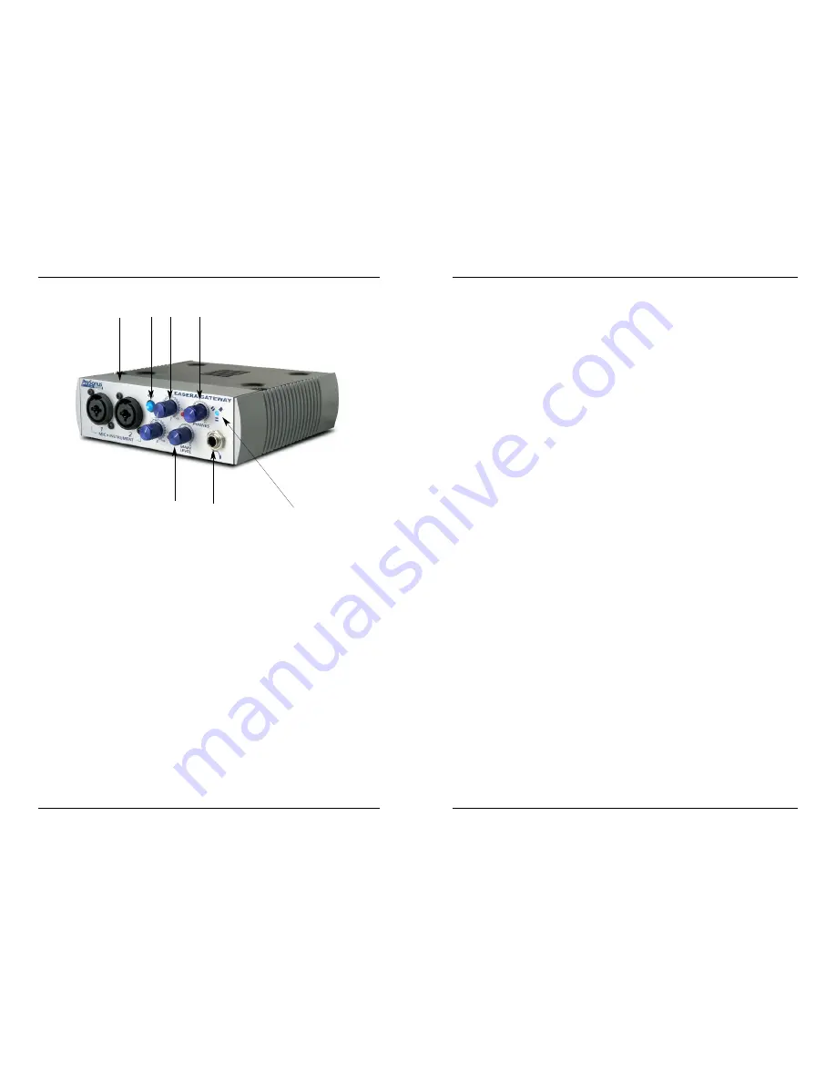
3.1 FRONT PANEL LAYOUT AND DESCRIPTION
1.Microphone / Instrument Pre-Amplifier.
Your EASERA GATEWAY is equipped with
two custom designed PreSonus microphone / instrument preamplifiers for use with all
types of microphones including Dynamics, Condensers, and Ribbons as well as instru-
ments and line level signals. The award winning PreSonus preamplifier design is a Class
A input buffer followed by a dual servo gain stage. This arrangement results in ultra low
noise and wide gain control allowing the EASERA GATEWAY user to boost desirable signal
without increasing unwanted background noise.
2. 48 Volt Phantom Power.
The EASERA GATEWAY has selectable 48V Phantom power
available for both preamps.
XLR connector wiring for Phantom Power
Pin 1= GND
Pin 2= +48V
Pin3= +48V
+22dBu Headroom.
The EASERA GATEWAY mic-pre has +22 dBu of headroom. This
feature gives you wide dynamic range and excellent transient response characteristics.
Neutrik Combo Connectors. Both preamps of the EASERA GATEWAY have a Mic/Line
connector using the Neutrik Combo connector. This revolutionary style connector lets you
use either ¼” phone or XLR connectors in the same female input.
INSTRUMENT INPUTS (Channels 1 and 2):
The ¼” TS connector on channels 1 and 2
are for use with an instrument (guitar, bass, and etc.). When an instrument is plugged into
the instrument input, the microphone preamplifier is bypassed and the EASERA GATEWAY
becomes an active instrument preamplifier.
NOTE: Active instruments are those that have an internal preamp or a line level output.
Active instruments should be plugged into a line input (3 or 4) rather than into an instru-
ment input. In other words, don’t plug an active instrument into the combo jacks on chan-
nels 1 or 2.
3. Input Gain/Trim Control.
This knob provides the following gain structure for each chan-
nel:
Microphone Input XLR: 45dB of variable gain (+14dB to +55dB)
Instrument HiZ Input TS ¼” (channels 1 and 2 only): 45dB variable gain (+8dB
to +50dB)
Clip Indicator. The clip indicator will light up if your input signal from the XLR
(Mic) or ¼” (line) r18dBu (0dBfs). At this level, your mic preamp/line trim
signal may not exhibit signs of clipping such as distortion. However, this level
would cause the A/D (analog to digital) converters to clip. Therefore it is highly
recommended that you do not allow your converters to clip (the clip indicators to
light up) as the sound quality would not be desirable.
4. Main Level.
This knob allows control over the output level for the MAIN CR OUTPUT 1
and 2 on the back of the EASERA GATEWAY. It has a range of -80db to +10dB.
5. Headphone Symbol and ¼” Jack.
This is where you connect your headphones.
6. Phones.
The Phones knob controls the amount of volume going to the headphone out-
put on the front of the unit. Notice the volume indicator goes to 11 (loud). Use this setting
with caution.
7. Red-Blue Power/Sync Light
. This light is a clock (sync) indicator. It lets you know if
your unit is receiving word clock correctly. Word clock is the manner by which digital
devices sync frame rates. Proper word clock sync prevents digital devices from having
pops, clicks, or distortion in the audio signal (due to mismatched digital audio transmission).
Blue – solid sync
Red – sync not present
Flashing Red and Blue – external sync not present
3 CONTROLS AND CONNECTORS
3 CONTROLS AND CONNECTORS
1
2
3
6
4
5
7


