background image


© Precor Incorporated, Unauthorized Reproduction and Distribution Prohibited by Law 

Page 129


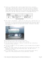
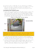
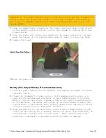
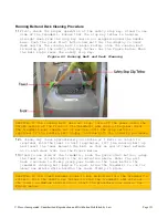
CAUTION: If the towel becomes loose it may be pulled into the treadmill’s 
rollers. Pull the safety key tether to stop the treadmill and retrieve 
the towel, no damage should occur. Start the procedure over again. See 
Figure Below. 

Keep one hand firmly grasped on the towel, use your other hand to pull 
on the safety stop key tether to stop the treadmill running belt. See 
Figure Below.  

Turn the power off. Place your hands on the towel and push it up and 
down the length of the running deck several times to clean the deck.  

Remove the towel. 


10 

Turn the power on.  


Monthly: (Plus Daily and Weekly Preventive Maintenance) 

Turn off power switch/circuit breaker, and unplug the power cord from 
the wall outlet. 

Clean the treadmill’s frame using a cloth dampened with water or a 
solution of SimpleGreen® and water (1 part SimpleGreen® to 30 parts 
Water). (Do not use acidic cleaners, and do not spray liquid directly 
on the machine). Use water and a soft nylon scrub brush to clean the 
top surface of the running belt, wiping excess water quickly so as not 
to allow liquid to flow underneath the belt. 

Wipe the surface of the electronic console with a damp sponge or soft 
cloth (Do not use acidic cleaners, and do not spray liquid directly on 
the machine), and dry with a clean towel.  Keep liquids away from 
electronic components to prevent electrical shock or damage. 

Summary of Contents for TRM10/GEN06

Page 1: ...Precor Incorporated Unauthorized Reproduction and Distribution Prohibited by Law Page 1 TRM10 GEN06 TREADMILL BASE 20039 165 REV A04 PRECOR CUSTOMER SUPPORT Service Manual...

Page 2: ......

Page 3: ...65761 16 Club Parameter Settings 5651565 17 Information Display 65 18 Section 6 Theory Of Operation 19 Consoles 19 Basic operation of a console 19 Consoles that could appear on the GEN 06 TRM10 Treadm...

Page 4: ...le Causes 46 Possible Remedies 46 Error 80 81 82 83 P30 Machine Controls Not Working 47 Description 47 Possible Causes 47 Possible Remedies 47 Troubleshooting the 3 Phase AC Drive Motor System 48 Proc...

Page 5: ...unications Error 66 Description 66 Possible Causes 66 Possible Remedies 66 Error 37 E Stop Not Communicating 67 Description 67 Possible Cause 67 Possible Remedies 67 Running Belt Deck Troubleshooting...

Page 6: ...edures 119 Adjusting Drive Belt Tension 119 Tensioning the Running Belt 122 Running Belt Tracking Adjustment 124 Running Belt Tracking Adjustment 124 Calibrating the Lift Motor 125 Section 10 Preventi...

Page 7: ...ur dealer for service This document contains information required to perform the majority of troubleshooting and replacement procedures required to repair and maintain this product This document conta...

Page 8: ...plied lubricants The use of these lubricants will quickly degrade the low friction surface of the deck Do not use petroleum based lubricants on mechanical components such as the lift as this may resul...

Page 9: ...anch circuit or a circuit equipped with a circuit breaker with a capacity of less than 20 amps the AC circuit must be corrected before any reliable troubleshooting can be performed on the treadmill Mo...

Page 10: ...soles Check the soles of your shoes and remove any embedded stones Tie long hair back Do not rock the unit Do not stand or climb on the handlebars display enclosure or cover Do not set anything on th...

Page 11: ...e odometer in the error log can help you determine age and relevance of the error 3 Clear the error log 4 Enter the Hardware Validation test by entering Diagnostic mode as follows 5 Press either the S...

Page 12: ...continually pressed 11 Press the INCLINE key while viewing the electronic console Confirm that the running deck returns to a level position and the incline display decrements to 0 as the INCLINE key i...

Page 13: ...ify the running belt drive system functions properly throughout the minimum to maximum range of control All drive system components deck belts rollers IFT are free of excessive noise vibrations or sme...

Page 14: ...Club Parameters and a Information Display Hardware Validation is a set of functional diagnostic tests that are useful in troubleshooting problems as well as verifying proper operation Club Parameters...

Page 15: ...creen will be the first screen you see when you approach the P80 console Press the Pause key and continue holding it down while you double press prior to 1 1 version software release or single press 1...

Page 16: ...ohibited by Law Page 14 Access Code Table Access Code Heading Name Function 5 1 7 6 5 7 6 1 Hardware Validation Running Diagnostic Tests 5 6 5 1 5 6 5 Club Parameters Commercial Changing Machine and o...

Page 17: ...Prohibited by Law Page 15 P20 Console Service Software Access The P20 console starts with STOP PAUSE or RESET however the numeric values of the service software code is assigned to the function keys i...

Page 18: ...Precor Incorporated Unauthorized Reproduction and Distribution Prohibited by Law Page 16 Hardware Validation Diagnostic Tests 51765761 Figure 3 Hardware Validation Graphic...

Page 19: ...et hatt hewor koutcanbepaused f or Fact or ydef aul ti s1 20 seconds SetM axCoolDown Ti m e Set st heam ountoft i m et hatacooldownper i od wi l loccurat t heend ofever ywor kout Fact or ydef aul ti s...

Page 20: ...e Di spl ayst hecur r entver si onofsof t war et hathandl esf l ashupgr adesof upperPCA consol e sof t war e UpperBaseSof t war e Di spl ayst hecur r entver si onofsof t war el oaded i nt heupperPCA...

Page 21: ...tests settings and information The keypad functions can vary between different console models however the basic functions that all consoles have are Quick Start Incline up or down and Speed up or dow...

Page 22: ...Precor Incorporated Unauthorized Reproduction and Distribution Prohibited by Law Page 20 Consoles that could appear on the GEN 06 TRM10 Treadmill Base Figure 4 Commercial Treadmill Consoles...

Page 23: ...Precor Incorporated Unauthorized Reproduction and Distribution Prohibited by Law Page 21...

Page 24: ...a machine function to take place via the keypad the console processor communicates the request to the processor in the lower electronics module Once the lower processor receives the request the lower...

Page 25: ...the United States Figure 6 NEMA Compatible Plugs 120v power when measured from hot to neutral should read between 90 and 132v 240v power when measured from hot to neutral should read between 180 and 2...

Page 26: ...operate on 5V DC however the lower control module sends 8 5V DC due to the optional external equipment such as Fitlinxx that may be connected to the CSAFE Communication Standard for All Fitness Equip...

Page 27: ...ontrolled by the voltage current applied to the 3 windings The windings stator and rotor core of the motor are designed to spin at a specific speed at the design frequency This is by design of the mot...

Page 28: ...fluid motion Mechanical balance is achieved by balancing the weight of the flywheel and electrical balance is achieved by all 3 windings being equal same number of ohms Other features of this AC driv...

Page 29: ...or the treadmill has been resumed after being paused the treadmill starts at 1 mph The user will then have 60 seconds to enter any remaining workout settings before motion detection begins Once motion...

Page 30: ...he motor in 2 directions the AC motor has 2 separate windings one for up and one for down AC1 has a continuous connection to the center common connection of the motor The system has a 2A fuse to prote...

Page 31: ...ution Prohibited by Law Page 29 Since the lift motor runs directly on the AC line voltage coming into the unit it is important to note that the lift motor is a different part number for a 120v unit th...

Page 32: ...ift This variable voltage is applied to the input of a 16 bit A D converter which converts the analog voltage into a 16 bit binary numeric representation that the processor can understand As the volta...

Page 33: ...ature 70 Introduction to Treadmill Troubleshooting The failure that is reported by the user may differ from your observations as a trained technician That is why it is important to validate the report...

Page 34: ...C receptacle If AC line voltage is present then the treadmills are sharing neutral lines If YES advise customer to have their facility wiring upgraded per Precor specifications and then continue to st...

Page 35: ...is idle Measure the line voltage with the treadmill circuit breaker is turned ON but the running belt is idle Make note of the voltage Then measure the voltage again using the instantaneous voltage d...

Page 36: ...on and Distribution Prohibited by Law Page 34 sometimes in months rather than years It is often accompanied by error codes 27 28 or 29 Perform an amp draw test by following troubleshooting procedure R...

Page 37: ...the AC voltage at the output side of the line filter with a voltmeter Verify that line voltage is present when the breaker switch is turned on If NO Replace the line filter If Yes continue with the fo...

Page 38: ...he 10 most resent errors with error location one being the most recent Not all system issues will generate an error code only the errors that can be generated in the treadmill will be described in thi...

Page 39: ...Precor Incorporated Unauthorized Reproduction and Distribution Prohibited by Law Page 37 Figure 10 Standard Error Codes_Flow Chart...

Page 40: ...ted with the error code Potential causes for the error codes will be listed with the most likely cause first and the least likely cause listed last It must be understood that this document can not ant...

Page 41: ...tr ecei vi ngdat af r om l owerPCA Er r or31 Faul t ydat ar ecei ved f r om l owerPCA Er r or32 LowerPCA notr ecei vi ngdat af r om upperPCA Er r or33 Faul t ydat ar ecei ved f r om upperPCA Er r or37...

Page 42: ...the service access software per the procedure in section 5 5 1 7 6 5 7 6 1 Hardware Validation Tests and verify that the machine belt speed and incline functions are working normally NOTE If a failure...

Page 43: ...p This test is performed because a permanently stuck key will inhibit the correct operation of the unit Possible Causes 1 A key on the display housing is permanently stuck in the operated condition 2...

Page 44: ...message almost always indicates a lower PCA problem when it is consistently displayed Failures causing this error message to be displayed are rare Possible Remedy If the error message is consistently...

Page 45: ...it to be too low Possible Remedies 1 If the error message is consistently displayed when the unit is powered up the lower PCA should be replaced It is possible to see this message displayed intermitt...

Page 46: ...ltage power was more than the DB system could absorb at once The power reservoir is also fed by the input line voltage so it is also possible that a temporary line voltage surge could result in an Err...

Page 47: ...the treadmill at moderate speed 7 or 8 MPH with the incline at 0 Is it possible to induce an Error 15 within 30 seconds o If YES replace the IFT drive and DB resistor o If NO proceed with next step T...

Page 48: ...C wiring and or is drawing high current 2 Treadmill is operating on a non dedicated circuit Possible Remedies 1 Voltage drop across the AC input wiring is a product of the length of the wire run and...

Page 49: ...P30 Lift Up Not Working Error 81 P30 Lift Down Not Working Error 82 P30 Speed Up Not Working Error 83 P30 Speed Down Not Working Possible Causes 1 Machine control interconnect cable has come unplugge...

Page 50: ...own Therefore the voltage readings in the following step must be taken within the first couple of seconds after the treadmill is instructed to start the running belt A multi meter with a hold feature...

Page 51: ...gs are significantly high or open replace the drive motor 6 If the ohm readings are correct inspect the female terminals of the drive motor connector Verify that they are not spread beyond the point o...

Page 52: ...Precor Incorporated Unauthorized Reproduction and Distribution Prohibited by Law Page 50 Figure 12 Lower Control Module Connector Numbering...

Page 53: ...otor could be bad 3 The lower control module could be bad Possible Remedies 1 Cycle the power on the lower control module by setting the units breaker switch to OFF and then ON again 2 Test the drive...

Page 54: ...are sets a maximum amount of allowable drive motor current This error indicates that maximum drive motor current has been reached Possible Causes 1 The running belt and or running bed is badly worn Po...

Page 55: ...mounted on the lower control module to ensure that the fan is not clogged with dust Thoroughly clean the fan and ensure that it spins freely Insure that machine motor cables are not routed to close a...

Page 56: ...is causing the high power demand Possible Remedies 1 Call Precor support for lower board built specifically to handle generator power 2 The outlet is not on a dedicated 20 amp branch circuit Using an...

Page 57: ...ntiometer The error log will help determine which is causing the issue Press and hold the reset key for at least 6 seconds if there are errors logged in the error log this action will take you into th...

Page 58: ...le to move 3 The lower control module is bad 4 The lift capacitor is bad 5 A lift motor winding is bad Possible Remedies 1 Remove power from the unit Remove the screw from the back of the lower contro...

Page 59: ...t is jammed against the motor housing rotate the lift nut or lift tube away from the motor housing If the lift was jammed please refer to step 3 before you continue Calibrate the lift motor per the pr...

Page 60: ...also fail in an open condition If this happens the lift will not operate in one direction Perform the following steps to determine if the switch is open With the incline below 15 to allow room for lif...

Page 61: ...ifies that the DOWN triac switch is working properly o If either of these conditions fail the lower control module must be replaced 4 The lift capacitor mounted inside the lift motor If the lift capac...

Page 62: ...ill in the manual program and press the INCLINE key The AC voltmeter should read between 1 5 to 2 0 times the AC line voltage If this reading is significantly low replace the lift motor Note that the...

Page 63: ...upper and lower numerical limits If the lift position number is found to be outside of the set limits error 42 will be displayed When troubleshooting an error 42 it is important to be aware of the ac...

Page 64: ...error 42 occurs while the lift is within its normal physical range Carefully inspect the lift potentiometer connector repair the poor connection if possible If the intermittent connection cannot be f...

Page 65: ...otentiometer resistance black to white 20 of black to red approximately 200W Potentiometer voltage black to red approximately 3 3 volts Potentiometer voltage black to white 20 of black to red approxim...

Page 66: ...s 1 Due to the high sensitivity of the 16 bit A D converter vibration during foot plant can cause the A D value to change enough to generate this error This condition is most likely to occur while the...

Page 67: ...r would typically happen when the lift was already in motion typically downward when a lift command in the opposite direction lift up was issued Some motors exhibited a very long turnaround time and t...

Page 68: ...lugged into the CSAFE connector 3 5V DC power supply is being overloaded by another component that is plugged onto the lower PCA 4 A defective lower control module 5 A defective upper PCA Possible Rem...

Page 69: ...upper PCA in the console did not know about it The system uses pin 8 of the data cable to communicate E Stop states between the console and the lower control module Possible Cause 1 Out of date softwa...

Page 70: ...s with the user s weight you should perform the AC input current measurement test on a new running belt and deck combination That will provide you with a benchmark reading to account for your individu...

Page 71: ...placed if the running deck has been previously flipped See Procedure Running Belt and or Deck Replacement on page 111 for running belt and running deck replacement 4 If the average AC current readings...

Page 72: ...me number of pins as the connector for the heart rate grips and you need to make sure that they were not reversed If the cables were reversed swap the connectors and re test If the cables were correct...

Page 73: ...Hall Effect sensor mounted to the drive roller bracket of the frame Check the alignment and gap 3 16 between the Auto Stop magnet holder and the Auto Stop sensor If the alignment and gap are not corr...

Page 74: ...ep 10 If the 5 volts is not present or the voltage is still significantly low replace the console or upper PCA If 5 volts is present permanently replace the Auto Stop cable Note The running belt does...

Page 75: ...y Auto Stop sensor 5 Damaged or missing Auto Stop magnet 6 The gap or alignment between the Auto Stop magnet and sensor is incorrect Possible Remedies 1 Check that the Auto Stop cable connectors are s...

Page 76: ...oles displayed NO USER DETECTED disconnect the Auto Stop cable from the Auto Stop sensor and check for 5vDC between the red and black wire If 5VDC is present replace the Auto Stop sensor 5 Ensure the...

Page 77: ...fy the Auto Stop hardware components are installed onto the treadmill frame The Auto Stop feature was not on the TRM as a standard feature until 12 28 2010 but may have shipped with a P80 console prio...

Page 78: ...o Stop sensor test will count the number of times the magnet crosses the sensor The P10 P20 and P30 consoles will display USER DETECTED if motion is detected from the running deck or NO USER DETECTED...

Page 79: ...es not function correctly continue with step 3 3 Verify that the HHHR board has the correct operating voltage Connect a voltmeter to VCC and Ground on the Power Signal connector The voltage should rea...

Page 80: ...ct a voltmeter to VCC and Ground on the Power Signal connector The voltage should read between 4 5 and 5 5VDC 3 Identify other sources of wireless interference signals in close proximity to the unit s...

Page 81: ...otor 93 Replacing the Incline Platform 96 Replacing the Power Control Module 98 Replacing the End Cap or Belt Guard 100 Drive Belt Replacement 102 Replacing the Drive Roller 105 Take Up Roller Replace...

Page 82: ...nect the AC line cord from the input module 7 Feed the end of the replacement AC line cord that mates with the input module through its hole in the frame and firmly insert it into the input module 8 S...

Page 83: ...ws that fasten the AC input panel to the frame 4 Disconnect the wiring from the circuit breaker 2 blue wires on 120 Vac treadmills or 2 blue and 2 brown wires on 240 Vac treadmills Note The figure bel...

Page 84: ...eaker and the blue wire from the AC line filter to the LOAD terminal on the circuit breaker On 240 Vac treadmills connect the blue wire from the input module to the upper LINE terminal on the circuit...

Page 85: ...the circuit breaker and replace the screws removed in step 6 NOTE On 120 Vac and 240 Vac treadmills connect the blue wire from the power control module to the L1 terminal on the LOAD side of the AC li...

Page 86: ...Distribution Prohibited by Law Page 84 8 Set the input panel in its mounting position and fasten it with the hardware removed in step 3 9 Thoroughly check the treadmill per Checking Treadmill Operati...

Page 87: ...ut panel to the frame Figure 25 AC Input Panel 4 Lift the AC input panel from the frame and rotate it to expose the AC line cord clamp screws and input module screws Figure 26 AC Input Panel Hardware...

Page 88: ...p 7 to terminal N the brown wire to terminal L and the green yellow wire to terminal E of the input module Figure 27 Input Module Wiring 11 Insert the AC line cord firmly into the input module Set the...

Page 89: ...nment tab from the inside of the frame mounting holes The Auto Stop Assembly should disengage from the frame Figure 28 Auto Stop Sensor Mounting 4 Position the replacement auto stop assembly with the...

Page 90: ...Precor Incorporated Unauthorized Reproduction and Distribution Prohibited by Law Page 88 7 Replace the motor hood...

Page 91: ...t far enough to expose the front right edge of the running deck Left and Right side orientations are based as if you were standing on the treadmill facing the console Figure 29 Running Deck Removal 5...

Page 92: ...an alignment mark on the top of their housings The magnet mark and the auto stop mark should align and the gap should be approximately 3 16 of an inch between the housings A 3 16 allen wrench can be...

Page 93: ...Precor Incorporated Unauthorized Reproduction and Distribution Prohibited by Law Page 91...

Page 94: ...ting plate for reference when you install the new motor 6 Remove the four bolts that fasten the drive motor to the frame 7 Set the replacement drive motor in its mounting position and fasten the drive...

Page 95: ...replacement incline motor must be calibrated prior to installation 1 Set the treadmill s circuit breaker in the off position and remove the AC line cord from the AC outlet 2 Disconnect the incline mo...

Page 96: ...Lift Motor Figure 33 Power Control Module 4 Either lay the treadmill on its side or securely block the front of the treadmill so that the treadmill s weight is off of the incline platform 5 Remove the...

Page 97: ...tate it in the direction that will cause the least amount of rotation to make alignment possible 8 Connect the frame ground wire to the treadmill frame with the screw removed in step 5 Route both incl...

Page 98: ...incline motor must be re calibrated per Procedure Calibrating the Incline Motor 4 Remove the two large hitch pins one each side from the incline platform to frame mounting See Figure Below Remove the...

Page 99: ...calibrate the incline motor per Procedure Calibrating the Incline Motor at this time Figure 35 Incline Mounting Pin 8 Fasten the incline tube to the incline platform with the clevis pin and hitch pin...

Page 100: ...line cord from the AC outlet 2 Remove the treadmill s hood 3 Disconnect the COMM INCLINE INPUT DB and OUTPUT connectors from the power control module Figure 36 Power Control Module 4 Remove the four...

Page 101: ...ved in step 4 7 Reconnect the COMM INCLINE INPUT DB and OUTPUT connectors removed in step 3 The mating connectors on the power control module are polarized therefore they cannot be reconnected incorre...

Page 102: ...he treadmill circuit breaker in the off position and unplug the treadmill s line cord from the AC outlet 2 Remove the four screws 2 lower screws each side that retain the end cap Do Not loosen or move...

Page 103: ...Figure 39 Belt Guard Mounting 4 Press inwards on the belt guard to remove the belt guard s tabs from the take up roller mounts Slide the belt guard off of the treadmill 5 Slide the replacement belt g...

Page 104: ...roller from the treadmill using the drive belt as a handle 6 Place the new drive belt on the drive roller and use the drive belt as a handle to slide the drive roller through the running belt and into...

Page 105: ...ive Shaft Figure 41 Measuring Point Frame Cross Beam 11 Walk the drive belt onto the drive roller pulley by rotating the drive motor flywheel Be sure the belt is fully seated in the grooves of both pu...

Page 106: ...re Tensioning the Running Belt on page 122 and Running Belt Tracking Adjustment as per procedure Running Belt Tracking Adjustment on page 124 14 Replace the belt guard ensuring the belt guard tabs are...

Page 107: ...up roller bearing failure Drive Roller Removal 1 Remove the end caps from the rear of treadmill to expose the take up roller mounting bolts Remove the treadmill s motor cover 2 Remove the deck trim f...

Page 108: ...cing should be the same on each side of the running belt to the edge of the running deck 8 Start tightening the left and right side drive roller mounting bolts Move back and forth between the left and...

Page 109: ...e left side drive roller shaft to frame This will ensure that the drive roller is parallel and square to the front of the frame Figure 43 Measuring Point Drive Shaft Figure 44 Measuring Point Frame Cr...

Page 110: ...3 Tensioning the Running Belt as per procedure Tensioning the Running Belt on page 122 and Running Belt Tracking Adjustment as per procedure Running Belt Tracking Adjustment on page 124 14 Replace the...

Page 111: ...rect drive belt and running belt tension Improper tensioning of the belt will lead to premature running belt wear premature driver roller bearing failure and premature take up roller bearing failure 1...

Page 112: ...ning belt is in the center of the deck the spacing should be the same on each side of the running belt to the edge of the running deck 8 Move the running belt so that the seam is underneath the treadm...

Page 113: ...t tension Improper tensioning of the belt will lead to premature running belt wear premature driver roller bearing failure and premature take up roller bearing failure 1 Remove the end caps from the r...

Page 114: ...ohibited by Law Page 112 4 Remove the four bolts and the roller guard that hold the deck to the frame Figure 48 Running Deck Bolts Plates 5 Remove both take up roller mounting bolts Remove the take up...

Page 115: ...emove the Auto Stop magnet from the deck if applicable Slip the running belt off the deck and discard Remove the inserts from the deck and flip it over re insert inserts into the new deck surface If t...

Page 116: ...Precor Incorporated Unauthorized Reproduction and Distribution Prohibited by Law Page 114 Figure 51 Running Belt Direction...

Page 117: ...Stop Assembly 12 Slide the take up roller though the running belt and positing in the frame Hand tighten the mounting bolts into the take up roller shaft 13 Align the bottom plate and pivot bracket h...

Page 118: ...unds 18 Position the drive belt around the drive roller pulley Use drive belt as a handle to assist in sliding the drive roller through the running belt and into the frame Hand tighten the mounting bo...

Page 119: ...e left side drive roller shaft to frame This will ensure that the drive roller is parallel and square to the front of the frame Figure 54 Measuring Point Drive Shaft Figure 55 Measuring Point Frame Cr...

Page 120: ...erneath the treadmill 26 Tensioning the Running Belt as per procedure Tensioning the Running Belt on page 122 and Running Belt Tracking Adjustment as per procedure Running Belt Tracking Adjustment on...

Page 121: ...ssemble the running belt deck drive motor rollers and all associated parts In This Section Adjusting Drive Belt Tension 119 Tensioning the Running Belt 122 Running Belt Tracking Adjustment 124 Calibra...

Page 122: ...ation 5 Belt tension adjustment is made with the drive belt removed Walk the drive belt off the drive motor pulley and loosen the four drive motor mount bolts to allow forward and rearward motor base...

Page 123: ...ion Prohibited by Law Page 121 12 Torque the four drive motor mounting bolts to 204 in lbs 17 ft lbs 23 N m 13 Re install the hood 14 Plug the line cord into the wall outlet and set the treadmill circ...

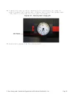
Page 124: ...rallel from each other The gauges have a fixed side and a movable side 3 Place the movable side to the middle of its travel and adjust the dial pointer to the number 3 NOTE Using the number 3 as a ref...

Page 125: ...by Law Page 123 5 Tighten the take up roller mounting bolts alternately in order to evenly tighten the running belt Tighten bolts until the gauges read 55 which is five and 1 2 lines past the number 3...

Page 126: ...wly turn the right side take up roller mounting bolt counterclockwise until the drifting stops The adjustments should only be done in 1 4 turn increments NOTE ONLY use the right side take up roller mo...

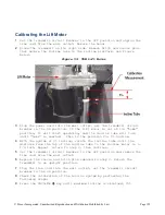
Page 127: ...sition it will start operating and the incline tube will turn until home is reached This is the position for 0 incline 4 With the system at 0 incline rotate the incline tube until the distance from th...

Page 128: ...horized Reproduction and Distribution Prohibited by Law Page 126 10 Press the INCLINE key until minimum incline is obtained 0 on TRM811 TRM 823 and TRM833 treadmills or 3 on TRM835 and TRM885 treadmil...

Page 129: ...rn or damaged The top side of the belt is a friction running surface and should NOT be used to indicate belt wear Belt wear is all about the under surface that touches the deck Any belt thought to be...

Page 130: ...safety stop key tether See the Figure Below When the belt stops reset the safety stop key Figure 60 Running Belt and Deck Cleaning CAUTION If the running belt does not stop turn off the power using th...

Page 131: ...the towel 10 Turn the power on Monthly Plus Daily and Weekly Preventive Maintenance 1 Turn off power switch circuit breaker and unplug the power cord from the wall outlet 2 Clean the treadmill s fram...

Page 132: ...the running deck and belt make sure that neither the bed or belt is worn or damaged If wear or damage is present replace using procedures outlined in the unit s service manual The top side of the belt...

Page 133: ...power cord The treadmill must remain out of service until the stop switch is repaired If the running belt stops continue with the cleaning procedure 12 A clean dry towel approximately 36 inches or 1...

Page 134: ...the towel and push it up and down the length of the running deck several times to clean the deck 16 Remove the towel 17 While in diagnostics run the belt speed test adjust the speed to 7 8mi hr Using...

Page 135: ...and belt with a dry cloth All outer surfaces of the unit are clean Inspect the power cord To Be Done Weekly All of the above plus Elevate the unit to maximum incline and remove power Totally clean th...

Page 136: ...properly Lift functions properly and does not make excessive noise or vibration Visually inspect the running belt for wear or damage Inspect the power cord for damage and make sure there is a power co...

Page 137: ...Precor Incorporated Unauthorized Reproduction and Distribution Prohibited by Law Page 135 In This Section Block Diagram 120 Volt 135 Block Diagram 120 Volt Section 11 Block Diagram...

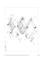
Page 138: ...Incorporated Unauthorized Reproduction and Distribution Prohibited by Law Page 136 In This Section Exploded View 136 Parts Identification List 142 Exploded View Section 12 Exploded View Parts Identif...

Page 139: ...Precor Incorporated Unauthorized Reproduction and Distribution Prohibited by Law Page 137 Exploded View...

Page 140: ...Precor Incorporated Unauthorized Reproduction and Distribution Prohibited by Law Page 138...

Page 141: ...Precor Incorporated Unauthorized Reproduction and Distribution Prohibited by Law Page 139...

Page 142: ...Precor Incorporated Unauthorized Reproduction and Distribution Prohibited by Law Page 140...

Page 143: ...Precor Incorporated Unauthorized Reproduction and Distribution Prohibited by Law Page 141...

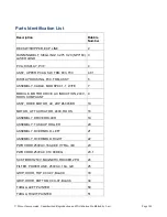
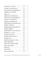
Page 144: ...MBLY CABLE MOD 8P8C 1 1 W FE 7 MODULE MOTOR DRIVE AC INDUCTION 240V ROHS COMPLIANT 9 ASSY DRIVE MOTOR AC 2HP 6305 BR 10 MOTOR LIFT ACTUATOR 240V ROHS 16 ASSEMBLY DRIVE ROLLER 19 ASSEMBLY TAKE UP ROLLE...

Page 145: ...HROOM HEA 59 PIN HITCH 125 DIA ZINC 216 60 WASHER FLT 5 16X 688X 065 ZN 61 SCREW SKHD 5 16 18X1 ZN MECH PLATI 62 ASSEMBLY REAR FOOT 63 BEARING FLANGE 875ODX 750IDX 50L 64 BUSHING SPANNER 65 SCREW HEX...

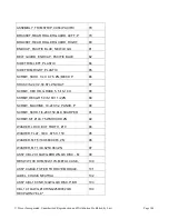
Page 146: ...SHCS 3 8 24 X 2 50 STL ZNCOAT 87 SCREW HEX HD GRADE 5 5 16 18 X 88 SCREW HEX GR 5 3 8 16X1 1 2 ZN 89 SCREW MACHINE 10 24X1 2 PANHD P 90 SCREW SKHD 1 4 20X1 50 BLK SHARPER 91 SCREW S T 10X 75 WSHHXHD...

Page 147: ...C CAT5E INLINE SNAP 114 COUPLER COAX F81 F F 75 OHM LONG BARREL 115 WASHER INTERNAL LOCK 384 ID 50 116 PLATE CONNECTOR COAX CAT5 117 NUT PANEL HEX 3 8 32 X 7 16 ZIN 118 CLIP ASSEMBLY 120 SWITCH MICRO...

Page 148: ...ND CBL 180 GEN06 ADT DRIVE 240V SPACER 181 SCREW S T 10X1 25 WSHHXHD ZN 182 HARDWARE KIT TRM10 200 LABEL HOOD ALUMINUM NEW LOGO 251 PLATE CONNECTOR COVER BLANK 252 CABLE P CLIP OPEN ENDED 0 375 BUND 2...

Page 149: ...porated Unauthorized Reproduction and Distribution Prohibited by Law Page 147 LOCKNUT STARWASHER 5 16 18 1 2 909 MACHINE SCREW 1 4 20 FLAT HEAD 910 WASHER 5 16 SPLIT LOCK ZINC 917 LITERATURE KIT TREAD...

Reviews: