


C844 Upright Cycle
Page 18
Procedure 5.3 - Inspecting and Adjusting the Gap Between
Upper and Lower Couplers
WARNING
Always turn off the C844 with the ON/OFF switch and unplug the power cord from the wall outlet
before you service the cycle.
Procedure
1.
Remove the upright covers from the pedestal weldment.
2.
Place a .060" feeler gauge between the upper and lower couplers.
3.
If the feeler gauge fits snugly
. . .
THEN . . .
OTHERWISE . . .
Remove the feeler gauge and rotate
Adjust the gap between the couplers
the couplers about 90 degrees.
as described in the following steps.
Re-check the gap between the couplers.
Rotate the couplers and check the gap
until you you have checked the gap between
the couplers at four different spots. Skip to
Step 8.
4.
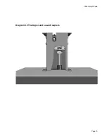
Remove the set screw that secures the upper coupler to the gear box (see
Diagram 5-3). If necessary, remove the old loc-tite from the set screw.
5.
Adjust the position of the coupler on the gear box shaft until the feeler gauge fits snugly
between the upper and lower couplers.
6.
Place a drop of blue loc-tite on the set screw removed in Step 4. Install the set screw into
the upper coupler.
7.
Rotate the couplers about 90 degrees, then return to Step 2.
8.
Install the upright covers on the pedestal weldment.
9.
Check the operation of the C844 as described in Section Four.