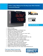
Helios Large Display Dual Analog Input Rate/Totalizer Instruction Manual
PD2-6262
6
Isolated
Transmitter
Power
Supply
Terminals P+ & P-: 24 VDC
10%. 12-24
VDC powered models selectable for 24, 10,
or 5 VDC supply (internal P+/P- switch).
85-265 VAC models rated @ 200 mA max,
12-24 VDC powered models rated @ 100
mA max, @ 50 mA max for 5 or 10 VDC
supply.
Non-Volatile
Memory
All programmed settings are stored in
non-volatile memory for a minimum of ten
years if power is lost.
Fuse
Required external fuse: UL Recognized, 5
A max, slow blow; up to 6 meters may
share one 5 A fuse
Normal Mode
Rejection
Greater than 60 dB at 50/60 Hz
Isolation
4 kV input/output-to-power line; 500 V
input-to-output or output-to-P+ supply
Overvoltage
Category
Installation Overvoltage Category II: Local
level with smaller transient overvoltages
than Installation Overvoltage Category III.
Environmenta
l
Operating temperature range:
-40 to
150°F (-40 to 65°C)
Storage temperature range:
-40 to
185°F (-40 to 85°C)
Relative humidity:
0 to 90% non-
condensing
Connections
Removable and integrated screw terminal
blocks accept 12 to 22 AWG wire.
Enclosure
Polycarbonate & glass blended plastic
case, color: gray
Mounting
Wall Mounting:
Four (4) mounting holes
provided for screwing meter into wall. See
Wall Mounting Instructions on page 10 for
additional details.
Pipe Mounting:
Optional pipe mounting
kit (PDA6260) allows for pipe mounting.
Sold separately. See Pipe Mounting
Instructions on page 11 for additional
details.
Tightening
Torque
Removable Screw Terminals:
5 lb-in
(0.56 Nm)
Digital I/O and RS485 Terminals:
2.2 lb-
in (0.25 Nm)
Overall
Dimensions
10.63" x 12.59" x 4.77" (270 mm x 319.7
mm x 121.2 mm) (W x H x D)
Weight
6.10 lbs (2.76 kg)
Warranty
3 years parts & labor
Dual Process Input
Two Inputs
Two
non-isolated
inputs, each
separately field selectable:
0-20, 4-20 mA,
10 V (0-5, 1-5, 0-10
V), Modbus PV (Slave)
Channels
Channel A, Channel B, Channel C
(Math channel)
Math
Functi
ons
Name
Function
Setting
Addition
(A+B+P)*F
Sunm
Difference
(A-B+P)*F
diF
Absolute diff.
((Abs(A-B))+P)*F
diFAbS
Average
(((A+B)/2)+P)*F
AvG
Multiplication
((A*B)+P)*F
nmulti
Division
((A/B)+P)*F
divide
Max of A or B
((AB-Hi)+P)*F
Hi-Ab
Min of A or B
((AB-Lo)+P)*F
Lo-Ab
Draw
((A/B)-1)*F
drAuw
Weighted avg. ((B-A)*F)+A
uw avg
Ratio
(A/B)*F
ratio
Concentration
(A/(A+B))*F
Concen
Total Addition
(tA+tB+P)*F
Sunm t
G. Tot. Addition (GtA+GtB+P)*F
SunmGT
Total Difference (tA-tB+P)*F
Dif t
G. Tot. Difference (GtA-GtB+P)*F
Dif GT
Total Ratio
(tA/tB)*F
Tratio
Total Percent
(tA/(tA+tB))*100
T PCT
Note: The F constant can be any value from
0.001 to 999.999. If the value is less than 1, it
will have the same effect as a divider. For
example, the average could also be derived
by using (A+B)*F, where F = 0.500.
Sequence of
Operations
for Input
Programmin
g
1. Select Input for A and B
2. Set up the rate, total, and grand
total engineering units for
channels A & B, and units for
math channel C
3. Set up rate, total, and grand total
decimal points for channels A &
B, and decimal point for math
channel C
4. Program channel A & B rate
parameters
5. Program channel A & B total and
reset parameters
6. Set up the display line 1 and line
2
7. Select the transfer function for A
& B (e.g. Linear)
8. Select Math function for Channel
C
9. Program constants for Factor (F)
and Adder (P).
10. Program cutoff values for A and B
Programmabl
e Constants
Constant P (Adder):
-99.999 to
999.999, default: 0.000
Constant F (Factor):
0.001 to
999.999, default: 1.000
Accuracy
±0.03% of calibrated span ±1 count,
square root & programmable
exponent accuracy, range: 10-100%
of calibrated span
Temperature
Drift
0.005% of calibrated span/
C max
from 0 to 65
C ambient,
0.01% of calibrated span/
C max from
-40 to 0
C ambient


