


2
Zenex Plus
User Manual
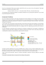
POWER-UP DISPLAY
Upon power-up the controller displays model name, Hardware Version
and Software Version for 2 seconds as shown in figure 2.1.
BASIC OPERATIONS
Section 2
RUN MODE
After the Power-up display the controller enters into RUN Mode. This is the normal operation mode wherein the controller
starts PV measurements, Alarm monitoring and Control Loop execution.
Main Screen
This is the default screen and its appearance depends upon whether a timer function is enabled or disabled as shown in the
figures 2.2 (a) & 2.2 (b) respectively.
Figure 2.2(a) : Timer Disabled
Figure 2.1
Figure 2.2(b) : Timer Enabled
°C
25.0
25.0
TEMP HIGH
SP
Measured Temperature
Alarm / Process
Status
Set Temperature
°C
25.0
25.0
0:10:00
SP
TEMP HIGH
Set Temperature
Measured
Temperature
Alarm / Process
Status
Balance Time
In case of measured value errors, the messages listed in Table 2.1 flash in place of process value as illustrated in Figure 2.3.
Message
Error Type
Cause
Sensor Open
Under-range
Over-range
RTD Pt100 / Thermocouple is Broken / Open
Temperature above Max. Specified Range
Temperature below Min. Specified Range
OPEN
Table 2.1
OVR
UNR
Figure 2.3
Note :
The Balance Time is shown in either HHH:MM or H:MM:SS
depending upon the remaining time counts as under :
HHH:MM for 249:59 to 10:00
H:MM:SS for 9:59:59 to 0:00:00
°C
OPEN
25.0
TEMP HIGH
SP
H/W Version
S/W Version
02
07