PPI Zenex Plus User Manual Download Page 17

15

Zenex Plus

User Manual


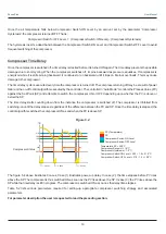
The zone at and above the boundary SP (

) is referred as Heat Pre-dominant zone and that below the boundary SP   


 (

is referred as Cool Pre-dominant zone. The controller automatically switches between the two zones depending upon the 

Temperature SP. If the Temperature SP is below boundary SP, Cool Pre-dominant zone is active and the compressor is kept 

ON. If the Temperature SP is at or above boundary SP, Heat Pre-dominant zone is active and the compressor is kept OFF. This 

strategy eliminates the need for the user to manually switch the compressor ON or OFF.

I

Control Zones

“Dual”; separate tuning can be performed in the Cool and Heat Pre-dominant zones for 

f the parameter 

 is set to 

accurate control in each zone. The controller maintains separate sets of Proportional Band, Integral Time & Derivative Time 

constants for each zone that are automatically selected and used by the controller depending upon the active zone.  

However, if the parameter 

Control Zones

 is set to “Single”; the controller uses a single set of Proportional Band, Integral Time 

& Derivative Time constants for both zones.

Figure 5.2

70°C 

0°C 

45°C 

30°C 

50°C 

Temp. Control SP in 

Cool Pre-dominant Zone

Temp. Control SP in 

Heat Pre-dominant Zone

Compressor Status

Boundary Set-point

ON

OFF


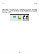
4.  PV Based Strategy


In this strategy, the compressor is switched to cool down the air temperature. The controller switches the compressor ON 

or OFF based on the comparison between the 

et  emperature values. Refer Figure 

 below.

Measured & S

T

5.3

The compressor is turned ON if the chamber air temperature value is above the Temperature SP by an amount set by the 

parameter 'Compressor Set-point'. That is;


Compressor Switch - ON Level   =  (Temperature SP) + (Compressor Set-point)

Figure 5.3

Measured Temperature
Temperature SP

Compressor Switch-ON Level
Compressor Switch-OFF Level

Compressor Switch-ON Level = 20.0 + 1.0 = 21.0°C 

Temperature SP = 20.0°C 
Compressor Set-point = 1.0°C 
Compressor Hysteresis = 1.2°C 

Compressor Switch-OFF Level = 21.0 - 1.2 = 19.8°C 

Compressor Status

OFF

ON

20.0

19.8

21.0

°C

Summary of Contents for Zenex Plus

Page 1: ...Zenex Plus User Manual User Manual Multi Purpose Temperature Controller with Graphic Display Zenex Plus...

Page 2: ...Zenex Plus User Manual CONTENTS 1 FRONT PANEL LAYOUT 1 2 BASIC OPERATION 2 3 OPERATOR PARAMETERS 5 4 SUPERVISORY PARAMETERS 7 5 FACTORY PARAMETER 12 6 PANEL MOUNTING AND ELECTRICAL CONNECTIONS 21...

Page 3: ...bol and the associated function 1 Section 1 The Controller front panel comprises of Graphic Readout and Membrane Keys as shown in Figure 1 1 below FRONT PANEL LAYOUT Table 1 1 Figure 1 1 Symbol Key Fu...

Page 4: ...d Figure 2 1 Figure 2 2 b Timer Enabled C 25 0 25 0 TEMP HIGH SP Measured Temperature Alarm Process Status Set Temperature C 25 0 25 0 0 10 00 SP TEMP HIGH Set Temperature Measured Temperature Alarm P...

Page 5: ...Version the screen shows Temperature Alarm Status Door Open Close Status the Heater Output Status ON OFF or Power Compressor ON OFF Status Figure 2 4 a Old Version Message String Alarm Process Status...

Page 6: ...epending upon the deviation of measured temperature value from the control setpoint and set limits The Controller provides a Digital Input for interfacing Door switch that senses the door position Ope...

Page 7: ...rator Parameter List Press Release ENTER Key until Desired Parameter appears Available only if Timer is Enabled These two commands are mutually exclusive Set toYes to startTimer if not already started...

Page 8: ...e value falls below this limit 0 2 to 99 9 Default 2 0 HI DEVIATION This Parameter sets a negative deviation offset limit with respect to the Control Set point The Alarm is activated if the measured t...

Page 9: ...HZ Proportional Band HZ Integral Time HZ Derivative Time Cycle Time Overshoot Inhibit Cutoff Factor Device ID Baud Rate Parity Serial Write Serial Parameter Zero Offset Sensor Input ENTER PASSWORD 0...

Page 10: ...UD RATE 2400 4800 9600 19200 38400 57600 Default 9600 Default 1 1 to 127 Parameter Description Settings Default Value PARITY One of the communication error trapping features Select the data packet par...

Page 11: ...eat Cool Control Compressor PV with based Strategy This Setpoint Value is compared with the process value to switch the compressor On Off with the set compressor hysteresis Default 45 0 0 0 to 100 0 F...

Page 12: ...to 999 9 Default 50 0 INTEGRAL TIME 0 to 3600 sec Default 100 sec DERIVATIVE TIME 0 to 600 sec Default 16 sec PROPORTIONAL BAND 0 1 to 999 9 Default 50 0 INTEGRAL TIME DERIVATIVE TIME 0 to 3600 sec De...

Page 13: ...ower per unit error Defined in same units and resolution as that for PV INTEGRALTIME Sets integral time constant in Seconds Setting the value to 0 cuts off the integral action DERIVATIVE TIME Sets der...

Page 14: ...elay Sec Timer Enable Start Band Holdback Strategy Hold Band Heat Off Cool Off Power Recovery Password Change Password HYSTERESIS 0 2 SELECT GROUP CTRL SENSOR INPUT First Group or First Parameter in s...

Page 15: ...C 200 to 1376 C 200 to 387 C Type R Rh 13 Type S Rh 10 Type B Type N 0 to 1771 C 0 to 1768 C 0 to 1826 C 0 to 1314 C RTD Pt100 1 C 0 1 C Reserved for customer specific Thermocouple type not listed ab...

Page 16: ...h heating cooling sources The user can enable any one or both outputs depending upon the test equipment type and application If both outputs are enabled by setting the parameter Control Strategy to He...

Page 17: ...pon the active zone However if the parameter Control Zones is set to Single the controller uses a single set of Proportional Band Integral Time DerivativeTime constants for both zones Figure 5 2 70 C...

Page 18: ...e compressor ON as and when the PV is above SP Figure 5 4 PV Temperature SP Compressor Switch ON Level Compressor Switch OFF Level Compressor Switch ON Level 20 0 1 0 21 0 C Temperature SP 20 0 C Comp...

Page 19: ...Cool Only Used in applications like Deep Freezer Cold Cabinet Lab Refrigerator etc that require lowering the temperature below ambient The Compressor control output switches cooling CMP source for mai...

Page 20: ...is paused if PV is outside holdband SP below Both Timer is paused if PV is outside holdband either above or below SP HOLDBACK STRATEGY Sets the temperature limit s with respect to the SP for the time...

Page 21: ...lt NO YES NO Set to Yes if is mounted for detecting Switch door Open Close position ENABLE FACTORY PASSWORD Parameter Description Settings Default Value CHANGE PASSWORD The Controller is shipped from...

Page 22: ...20 Zenex Plus User Manual FACTORY EXIT Parameter Description Select to quit mode and return to mode Setup Main Display EXIT SETUP MODE...

Page 23: ...ten the terminal screws while making connections 6 Make sure that the controller supply is switched off while making removing any connections or removing the controller from its enclosure CONNECTION D...

Page 24: ...17 18 19 20 21 22 23 24 25 26 27 B B 85 264 VAC Supply Pt100 TC L N RS485 Serial Heater Control Compressor Control Process Alarm Event Alarm B124 Door Open Timer Start Alarm ACK Zenex Plus 13 Pt100 2...

Page 25: ...Alarm Event Alarm Figure 6 5 23 24 25 22 14 15 16 13 Old Version New Version DI 2 DI 3 DI 1 Door Open DI 2 Timer Start DI 3 Alarm ACK DI 1 Figure 6 6 PC COMMUNICATION PORT The controller Communication...

Page 26: ...copper conductor wire of the size not smaller than 0 5mm for power supply connections ensuring proper polarity as shown in Figure 6 7 module The is not provided with fuse and power switch If necessary...

Page 27: ...p i i n d i a n e t Process Precision Instruments 101 Diamond Industrial Estate Navghar Vasai Road E Dist Palghar 401 210 Maharashtra India 0250 2391722 33 37 42 07498799226 09321985369 support ppiind...

Reviews: