


21
Zenex Plus
User Manual
WARNING
MISHANDLING / NEGLIGENCE
CAN RESULT IN PERSONAL DEATH
OR SERIOUS INJURY.
ELECTRICAL CONNECTIONS
1. The user must rigidly observe the Local Electrical Regulations.
2. Do not make any connections to the unused terminals for making a tie-point for other wires (or for any other reasons) as
they may have some internal connections. Failing to observe this may result in permanent damage to the controller.
3. Run power supply cables separated from the Sensor cables (Thermocouple / RTD). If the cables are run through conduits,
use separate conduits for power supply cable and low-level signal cables.
4. Use appropriate fuses and switches, wherever necessary, for driving the high voltage loads to protect the controller from
any possible damage due to high voltage surges of extended duration or short-circuits on loads.
5. Take care not to over-tighten the terminal screws while making connections.
6. Make sure that the controller supply is switched-off while making/removing any connections or removing the controller
from its enclosure.
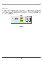
CONNECTION DIAGRAM
The Electrical Connection Diagram is shown on the Top (Old Version) or Back (New Version) side of the controller enclosure.
The diagram shows the terminals viewed from the
REAR SIDE
with the controller Front Label upright. Refer figure 6.2(a) for
Old Version & 6.2(b) for New Version.
Section 6
PANEL MOUNTING AND ELECTRICAL CONNECTIONS
PANEL CUTOUT
PANEL MOUNTING
Follow the steps below for mounting the instrument on panel :
1. Prepare a cutout to the size shown in Figure 6.1.
2. Remove the Panel Mounting Clamp from the instrument Enclosure.
3. Insert the rear of the enclosure through the panel cutout from the front of the mounting panel.
4. Fix the mounting clamp pair such that it ensures secured mounting of the enclosure against the panel wall.
Panel Cutout
75 X 152 mm
-0, +1.0 mm
Figure 6.1(a) : Old Version
Panel Cutout
75 X 150 mm
-0, +1.0 mm
Figure 6.1(b) : New Version