User Manual
ScanLog 96 Pen Drive Version
19
Disable
Enable
(Default : Disable)
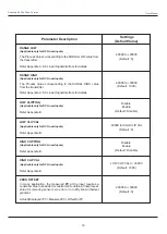
Parameter Description
Settings
(Default Value)
(Applicable only for DC Linear Inputs)
Refer Appendix-B.
LOW CLIPPING
(Applicable only for DC Linear Inputs)
Refer Appendix-B.
LOW CLIP VAL
-30000 to HIGH CLIP VAL
(Default : 0)
(Applicable only for DC Linear Inputs)
Refer Appendix-B.
HIGH CLIPPING
Disable
Enable
(Default : Disable)
(Applicable only for DC Linear Inputs)
Refer Appendix-B.
HIGH CLIP VAL
LOW CLIP VAL to 30000
(Default : 1000)
-30000 to +30000
(Default : 0)
RANGE LOW
(Applicable only for DC Linear Inputs)
The Process Value corresponding to the SIGNAL LOW value from
the transmitter.
Refer Appendix-A : DC Linear Signal Interface for details.
-30000 to +30000
(Default : 0)
-30000 to +30000
(Default : 1000)
RANGE HIGH
(Applicable only for DC Linear Inputs)
The Process Value corresponding to the SIGNAL HIGH value
from the transmitter.
Refer Appendix-A : DC Linear Signal Interface for details.
ZERO OFFSET
In many application, the measured
PV
at the input requires a
constant value to be added or subtracted to obtain a final process
value for removing sensor zero error or to nullify known thermal
gradient.
Actual (Displayed) PV = Measured PV + Offset for PV.


