20 - 80 kVA parallel UPS system
User’s and Installation Manual
1018390
Revision C
34
6.8 Installation check list
1.
Check that electrical connections to the installation site have been properly executed.
2.
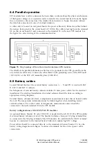
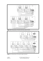
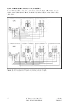
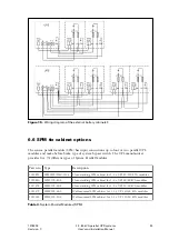
Check that input cables from a low-voltage switchgear are connected to the UPS
modules and the system parallel panel. Make sure that the neutral of UPS input is
properly connected.
A readily accessible disconnect device with a contact separation of at least 3 mm is
mandatory in the fixed input wiring of UPS modules. Use fuses or miniature circuit
breakers to protect cables from a short circuit.
3.
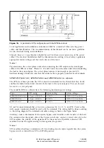
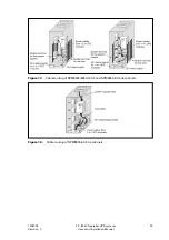
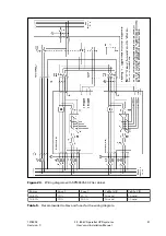
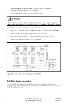
Check that the output cables of UPS modules are connected to the system tie panel.
Pay a special attention to the correct phase order because the system bypass and UPS
modules must have the same order of L1, L2 and L3 phases.
4.
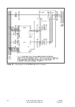
Check that the contact information of the system bypass switch is properly connected
to all UPS modules. Make sure the polarity of the information is correct. Cables are
delivered with the UPS modules.
5.
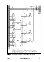
Check that the parallel information cable between UPS modules has been properly
connected in a ring configuration. Cables are delivered with the UPS modules.
6.
Since the UPS does not have automatic backfeed isolation a warning label must be
added on all primary power isolators installed remote from the UPS area to warn
electrical maintenance personnel that the circuit feeds a UPS. The warning label shall
carry the following wording or equivalent: ”ISOLATE UNINTERRUPTIBLE POWER
SYSTEM (UPS) BEFORE WORKING ON THIS CIRCUIT.”
The UPS system should be now connected to the mains and to the load but there is no power.
7. Communication interfaces
7.1 Overview
A single UPS module sends information about mains, load, and internal operation and status.
The information can be used in a computer to ensure a total protection of the critical
software and data. It is available in two RS232 serial communication ports, four potential
free relay outputs and four signal inputs. These communication interfaces are located behind
the door.
UPS modules are provided with a 230 VAC power supply (terminal X5) for use with internal
modem or portable computer. This power supply is protected with an automatic 10 A fuse
F3.
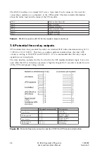
UPS modules are delivered with the relay adapter circuit board that converts the 16-pin
relay interface X102 to a 15-pin male D-sub terminal. It is used together with options such
as ‘Remote Status Panel’ and ‘Alarm Extension Unit’.

