20 - 80 kVA parallel UPS system
User’s and Installation Manual
1018390
Revision C
36
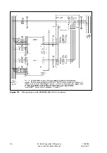
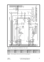
The RS-232 interface on terminal X101 uses a 9-pin male D-sub connector. It is used for
connecting a modem (or a computer) to the UPS module. The data includes information
about the utility, load and the status of the UPS module.
1
n
i
P
d
e
t
c
e
t
e
d
r
e
i
r
r
a
c
a
t
a
D
2
n
i
P
a
t
a
d
d
e
v
i
e
c
e
R
3
n
i
P
a
t
a
d
d
e
t
t
i
m
s
n
a
r
T
4
n
i
P
y
d
a
e
r
l
a
n
i
m
r
e
t
a
t
a
D
5
n
i
P
d
n
u
o
r
g
l
a
n
g
i
S
7
n
i
P
d
n
e
s
o
t
y
d
a
e
R
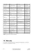
Table 8.
RS-232 connection (X101) for the modem, 9-pin male D-sub.
7.4 Potential free relay outputs
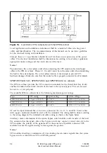
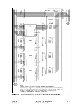
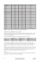
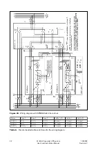
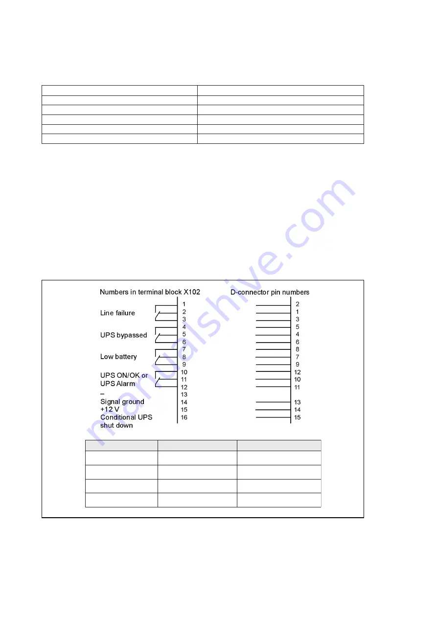
UPS modules have four potential free relays on terminal X102 with a maximum rating of 1A
/ 30VAC or 0.2A / 60VDC. They have a complete galvanic isolation from the other UPS
circuits according to IEC60950 and EN50091-1. It is recommended that the relay output
signals run as twisted pairs.
The relay interface includes the Pin 16, which is the UPS module shutdown input. It is active
only when the UPS is in battery operation. A high level signal for 5 seconds is needed to turn
off the UPS until proper voltage returns.
Figure 26.
Potential free relay output connection (X102) for UPS module information.
d
e
t
c
e
n
n
o
c
s
r
e
b
m
u
n
n
i
P
e
t
a
t
s
m
e
t
s
y
S
e
r
u
l
i
a
f
e
n
i
L
3
-
2
3
-
1
k
o
e
n
i
L
e
r
u
l
i
a
f
e
n
i
L
d
e
s
s
a
p
y
b
S
P
U
6
-
4
6
-
5
y
l
p
p
u
s
r
e
t
r
e
v
n
I
y
l
p
p
u
s
s
s
a
p
y
B
y
r
e
t
t
a
b
w
o
L
9
-
8
9
-
7
l
a
m
r
o
n
y
r
e
t
t
a
B
w
o
l
y
r
e
t
t
a
B
r
o
k
o
/
n
o
S
P
U
m
r
a
l
A
S
P
U
2
1
-
0
1
2
1
-
1
1
k
o
/
n
o
S
P
U
m
r
a
l
a
S
P
U

