20 - 80 kVA parallel UPS system
User’s and Installation Manual
1018390
Revision C
10
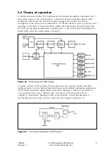
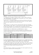
The mains is rectified and boosted to DC power in the rectifier part. The rectifier provides
power to the battery charger and the inverter load. The battery charger keeps the battery in
recharged condition with ABM™ technology. The DC Link connects the rectifier output with
the inverter input. It is the means for transferring power between these system components.
The output of the inverter is constantly maintained in phase synchronism with the bypass
supply voltage provided that it is within the voltage and frequency tolerances specified for
the load transfer condition. The inverter is changing the output operation to internal set
frequency if the bypass supply exceeds these tolerances.
In the event of a mains power interruption, the battery is supplying the inverter load. The
rectifier starts again to supply the inverter load when the AC mains power returns. The
battery charger is recharging the battery after the mains return, too.
The static switch is initiating uninterrupted transfer of the load to the bypass line when the
inverter is overloaded or the inverter is not able to feed the load. The output is protected
with a tripping circuit breaker to separate the faulty UPS module from the parallel load bus.
The parallel load sharing is implemented individually in UPS modules with Hot Sync™
technology. The critical load is supported even in the unlikely situation of the redundant bus
communication failure.
3.3 Sizing
The output power rating of the parallel UPS configuration should be specified according to
the total power demand of the protected load. Some margin should be allowed for potential
expansion, and for possible inaccuracy in calculating or measuring the actual power
requirement.
The battery should be sized according to the desired backup time. Note that the backup
time is longer if the load is less than the nominal power rating of the parallel UPS system.
3.4 Accessories
The following external options are available:
•
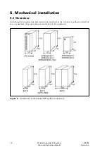
System Parallel Module (SPM):
– SPM9305 cabinet : 2-4 x 80 kVA
– SPM9305 cabinet : 2-4 x 20-60 kVA
– SPM9305/9340 cabinet : 2 x 80-130 kVA
– SPM9305 module : 2 x 40-60 kVA
– SPM9305 module : 2 x 20-30 kVA
•
Battery cabinets:
– BAT D, BAT E, and BAT F
•
Input filter:
– THDi 10%
•
ViewUPS:
– Remote status/control panel
•
LanQuattro:
– 4 x RS-232 data manager
•
ConnectUPS:
– SNMP adapter
•
Others:
– Engineered solutions upon request


