3
ASSEMBLY
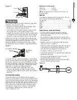
To adjust sanding belt table:
WARNING
To prevent trapping the workpiece or fingers between the
table and the sanding belt adjust the sanding belt table to
a maximum of 1/16" from the backstop.
• Loosen the locking lever and set screw. Slide the
sanding belt table in or out until it is 1/16" from the front
of the sanding belt. See Figure 5.
• Place a combination square on the table with the ruler
side against the back stop. Set the table 90° to the
backstop.
• Tighten the locking lever.
• Tighten the set screw.
• For Bevel Sanding, loosen the locking lever and tilt
the sanding belt table forward to desired position and
tighten locking lever.
REPLACING THE SANDING BELT
Refer to Figure 6, 7
NOTE:
This sander uses 1" x 30" sanding belts.
• Turn the machine "OFF", and disconnect the machine
from the power source before assembling the sanding
belt.
• Remove the belt guard locking knob and then remove
the side belt guard. See Figure 6.
• Remove the spark guard. See figure 6
Figure 6
Spark
Guard
Side Belt
Guard
• Turn the belt tracking knob counter clockwise to loosen
the belt tension and remove the old belt.
• Position the new belt on the wheels. Make sure the
directional arrows on the belt point in the same direction
as the arrows on the sander.
Figure 7
Sanding
Belt
Belt
Tracking
Knob
Wheel
Wheel
Wheel
• Turn the belt tracking knob clockwise until the belt
tracks to the center of the wheels.
• Replace the side guard and then spark guard.
• Ensure the sanding belt table measures a maximum of
1/16" from the backstop. To adjust see the
To Adjust
Sanding Belt Table
paragraph in this section.
SANDING BELT TRACKING ADJUSTMENT
Refer to Figure 2, 7
• Turn the machine "OFF", and disconnect the machine
from the power source.
• Remove the belt guard locking knob and then remove
the sander's side belt guard. See Figure 2.
• Rotate the sanding belt by hand to check the belt
tracking. The belt should track to the center of the
wheels.
– When looking at the front of the sander if the
belt tracks to the left, turn the tracking knob
counterclockwise until the belt tracks to the center of
the wheels.
– When looking at the front of the sander if the belt
tracks to the right, turn the tracking knob clockwise
until the belt tracks to the center of the wheels.
• Replace the side belt guards and secure in place with
the belt guard locking knob.
• Plug the power cord into the correct receptacle. (Refer
to
Power Source
paragraph in this section of the
manual.)
• Turn the switch ON and OFF to make sure the belt is
tracking at high speed; readjust with tracking knob if
needed.
Summary of Contents for BD1030
Page 10: ...1 x 30 BELT SANDER PARTS ILLUSTRATION 8 PARTS LIST 8 ...
Page 13: ...NOTE ...
Page 14: ...NOTE ...
Page 15: ...NOTE ...
Page 16: ...Southern Technologies LLC 3816 Hawthron CT Waukegan IL 60087 ...


