


9
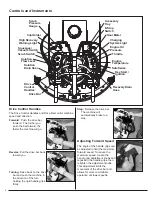
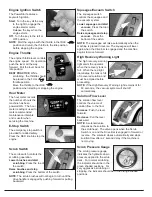
Engine Ignition Switch
The PowerStar features a
keyswitch ignition.
Start
: Turn the key all the way
to the right to engage the
engine starter motor.
Release the key when the
engine starts.
Off
: Turn the key to the left or
OFF position.
NOTE
: Start the engine with the throttle in the IDLE
position and return the throttle to the idle position
before stopping the engine.
Engine Throttle
The engine throttle lever controls
the engine speed. For operation,
push the lever all the way
forward. Pull the lever back for
idle position.
BEST PRACTICE
: While
scrubbing, the throttle should
be placed in the FULL
throttle position.
Move the throttle to the IDLE
position when starting or stopping the engine.
Hour Meter
The hour meter records
the number of hours the
machine has been
powered ON. The hour
meter reading is used to
mark recommended
maintenance intervals
and is useful when
servicing the machine.
E-Stop Switch
The emergency stop switch is
provided for added safety.
Press the RED knob to stop the
engine.
Scrub Switch
The scrub switch controls the
scrubbing operation.
Lower brushes and start
scrubbing
: Press the top of
the switch.
Raise brushes and stop
scrubbing
: Press the bottom of the switch.
NOTE
: The scrub brushes will not begin to turn until the
drive handle is engaged by pushing forward or pulling
backward.
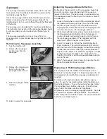
Squeegee/Vacuum Switch
The squeegee switch
controls the squeegee and
the vacuum system.
Lower squeegee and start
vacuum
: Press the top of
the switch.
Raise squeegee and stop
vacuum
: Press the
bottom of the switch.
NOTE
: The squeegee will raise automatically when the
machine is placed in reverse. The squeegee will lower
again when the drive bar is engaged and the machine
begins to move forward.
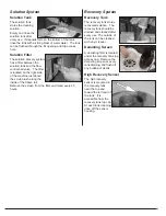
High Recovery Warning Light
The high recovery warning
light alerts the operator
when the recovery tank is
full. When the red light
illuminates, the tank is full
of recovered solution and
must be emptied before
proceeding.
NOTE
: If the High Recovery Warning Light remains lit for
60 seconds, the vacuum system will shut off
automatically.
Solution Flow Lever
The solution flow lever
controls the volume of
solution flow to the floor.
Increase
: Push the lever
forward.
Decrease
: Pull the lever
backward.
NOTE
: A solenoid valve
dispenses the solution to
the scrub head. The valve opens when the Scrub
Switch is on and the Drive Bar is engaged in forward or
reverse. The solenoid closes automatically and stops
solution flow after a 2 second delay if the machine is
not moving.
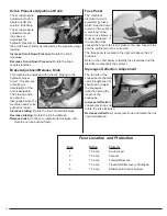
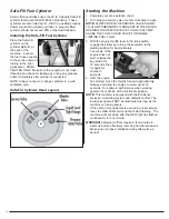
Scrub Pressure Gauge
The scrub pressure gauge
indicates the hydraulic down
pressure applied to the scrub
deck. For normal scrubbing,
the indicator should be in the
green shaded positions. For
very aggressive scrubbing or
stripping, the indicator should be in the orange shaded
positions.
Summary of Contents for Z1 PSZ133KWA
Page 3: ......
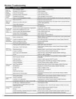
Page 19: ...16 Machine Troubleshooting...
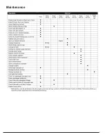
Page 20: ...17 Maintenance...
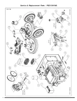
Page 27: ...Service Replacement Parts PSZ133KWA 031708 24...
Page 29: ...26 Wiring Schematic PSZ133KWA SAFE SENSE FOR MACHINES SERIAL NUMBER 62233 AND EARLIER 031708...
Page 30: ...27 Wiring Schematic PSZ133KWA ECO SENSE FOR MACHINES SERIAL NUMBER 62420 AND LATER 031708...
Page 32: ...29 Hydraulic Schematic PSZ133KWA 031808...
Page 33: ...30 Hydraulic Hose Connection Group PSZ133KWA 031808...
Page 35: ...32 Frame Wheel Group PSZ133KWA 031808...
Page 37: ...34 Power Group Engine PSZ133KWA 031808...
Page 39: ...36 Hydraulic Reservoir PSZ133KWA 031808...
Page 41: ...38 Airbox PSZ133KWA 031808...
Page 43: ...40 LP Regulator PSZ133KWA 031808...
Page 45: ...42 Scrub Deck Group PSZ133KWA 052308...
Page 47: ...44 Squeegee Lift Group PSZ133KWA 031808...
Page 53: ...50 Solution Tank PSZ133KWA 031808...
Page 55: ...Recovery Tank PSZ133KWA 52 030808...
Page 57: ...54 Engine Cover PSZ133KWA 031908...
Page 59: ...Squeegee 45 PSZ133KWA 56 031908...
Page 61: ...58 Control Panel Bulkhead Group PSZ133KWA 031908...
Page 63: ...60 Operational Controls PSZ133KWA 031908...
Page 67: ...64 Relay and Timer Group PSZ133KWA 031908...
Page 73: ...70...


