powersoft M-Drive IK User Manual Download Page 35

M-Drive DSP initialization  |  25

16 : 5.6. Internal parameters

Click on the cogwheels button to access the Internal parameters window.

16 : 5.5. Pressure Model Operating Mode

The amplifier’s output signal is modified in real time as a result of the combination of the input audio signal and the feedback 

loop. The alteration is applied to the input stage so to minimize the difference between the desired output and that measured 
and reported by interpolating two the feedback loops.

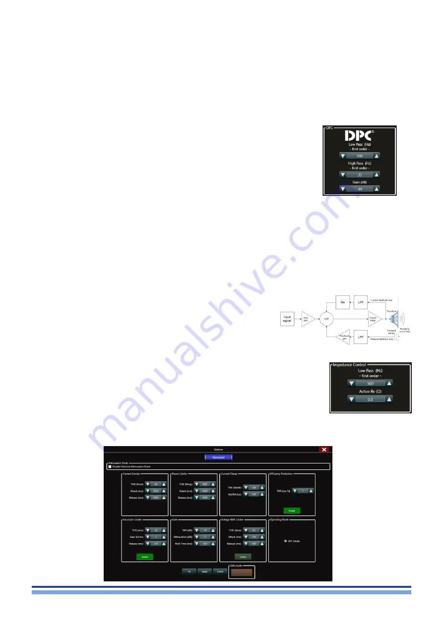
16 : 5.5.1. Pressure Control (pressure feedback loop)

This loop brings the pressure level measured at the radiating sound field, back to the input stage. This is achieved by 

feeding the pressure sensor measurement through a first order low pass filter (LPF) and a linear amplifier. The parameters that 
can be set by the user for this feedback-loop therefore are:

f

f

The loop gain, expressed in dB and limited by the system’s stability, defining the 
strength of the feedback effect;

f

f

The LPF bandwidth, defining the top frequency of the band at which this feedback loop 
is active;

f

f

The HPF bandwidth, defining the bottom frequency of the band at which this feedback 
loop is active.

It is important to set the loop gain carefully, as too high a value will bring the system to instability. This results in a loud 

“ship’s horn” sound which can potentially damage the system if not silenced after a short time. This can be done by lowering 
the feedback loop gain until the sound stops. The entire pressure feedback loop can be bypassed by entering

16 : 5.5.2. Impedance Control (current feedback loop)

This loop brings back a voltage signal proportional to the current present at the output stage to the system’s input. The 

signal taken from the output is first filtered by a first order low pass filter. Following this step, the current/voltage translation is 
carried out by a virtual resistor named “Re”. The importance of this series resistor relies in the difference between traditional 
transducers and M-Force.

M-Force has an extremely low impedance. This means that they manifest a 

violent, extremely high Q resonant peak which can result in an unnatural sound 
reproduction. By adding a virtual series resistor Re, the entire system’s resonant 
peak will be slightly flattened and widened in a way that mimic’s a traditional 
speaker’s lower Q resonance. This resistor will however not affect the power 
transfer from input to output as this is not a “real” physical resistor subject to 
ohmic heating. The parameters the user can set for this feedback loop therefore 
are:

f

f

The “added Re” value, defining the additional series resistor inserted to simulate a traditional 
speaker behavior. This is usually a small number, which aims to return the apparent 
loudspeaker resistance to a traditional 2-4 Ohm value;

f

f

The LPF bandwidth, defining the range of frequency at which this feedback loop is active.

Summary of Contents for M-Drive IK

Page 1: ...Keep this manual for future reference 2019 Powersoft USER GUIDE M Drive DO000184 00 R02...

Page 2: ...powersoft_MDrive_UG_EN_R02 Data are subject to change without notice For latest update please refer to the online version available on www powersoft audio com...

Page 3: ...1 6 PL22 PL23 pinout 8 11 7 PL21 pinout 9 11 8 SO5 pinout 10 12 Hardware protections 12 12 1 Thermal Protections and Fan Control 12 12 2 Power supply protections 12 12 2 1 Primary AC mains overcurrent...

Page 4: ...Required Tools 33 21 2 Connection 33 21 3 DSP 4 initialization as Powersoft model 33 22 Programming DSP 4 35 23 Export Custom Preset 36 24 Creating Custom Model DSP 4 37 24 1 Custom model builder 37 2...

Page 5: ...nce with Powersoft s instructions 7 Do not install near any heat sources such as radiators heat regis ters stover or other apparatus that produce heat 8 Do not defeat the safety purpose of the polariz...

Page 6: ...ntervention d un technicien est n cessaire dans les cas suivants le cordon d alimentation ou la prise secteur sont endommag s des corps trangers ou du liquide se sont introduits dans l appareil l appa...

Page 7: ...nico debe realizarlo siempre personal cualificado Se requerir servicio de asistencia t cnica cuando el aparato sufra alg n tipo de da o como por ejemplo que el cable de alimentaci n o el enchufe est n...

Page 8: ...NON CI SONO PARTI INTERNE AD USO DELL UTENTE RIVOLGERSI A PERSONALE QUALIFICATO PER L ASSISTENZA NON ESPORRE QUESTO APPARECCHIO ALLA PIOGGIA UMIDIT O SOSTANZE LIQUIDE OGGETTI PIENI DI LIQUIDI COME VA...

Page 9: ...sent to separate col lection facilities for recovery and recycling By separat ing this product from other household type waste the volume of waste sent to incinerators or land fills will be reduced an...

Page 10: ...amage which is invisible This internal damage can then cause electrical failure or reliability problems It is recommended that all workstations where Electrostatic Discharge Sensitive devices ESDS and...

Page 11: ...conditions Thanks to this innovative approach to full boundary conditions feedback processing the DPC dramatically improves the electroacoustic efficiency in terms of high SPL and sonic performance o...

Page 12: ...resistance offers high heat dissipation as well as a low electric resistance allows high current flow through a conductive wire In order to define the maximum allowed thermal resistance for the heatsi...

Page 13: ...Thermal constrains 3 FIGURE 2 M Drive IK heat sink with powerCON and AC Mains filter 85 81 168 N 6 HOLES 6 5 138 10 654 612...

Page 14: ...gs into the amplifier Placing the ferrite elsewhere on the cable noticeably reduces its effectiveness 9 4 Chassis shielding If not already present on the product a full body metal chassis or a shieldi...

Page 15: ...Mechanical drawings 5 10 Mechanical drawings FIGURE 7 M Drive mechanical drawing all dimensions in millimetres threaded M3 max depth 3mm torque 0 8 0 1 N m 70...

Page 16: ...6 M Drive User guide 90 FIGURE 8 Pressure sensor all dimensions in millimetres unless otherwise stated FIGURE 9 DPC interface board all dimension in millimetres 2 5 m...

Page 17: ...ent 8 pin Micro Match Socket CN109 Pressure sensor input 10 pin Micro Match Socket CN101 RS 485 FL0IS315 Interface 16 pin Micro Match Socket CN102 FL0IS315 Interface 18 pin Micro Match Socket FIGURE 1...

Page 18: ...ut to external FAN s 24Vdc 100mA MAX current total PL23 the polarity is directly dependant on the positioning and configuration of the pressure sensor and motor Check Chapter 14 for more detailed info...

Page 19: ...0 17VDC min 1VDC max Scale Factor 40A V 4 5K 12 TEMPMON OUT Output temperature monitor 0 5VDC Scale factor Temperature dependant 7K 25 C 13 12VDC PWR Regulated 12VDC supply 5 MAX current tot 0 5A Pro...

Page 20: ...us active Apply 4 7k external resistor 18 21 RESERVED 22 GND PWR Ground 0V 23 27 NC 28 TEMPMON OUT Output temperature monitor 0 3 3VDC Scale factor See TEMPMON table 29 GND PWR Ground 0V 30 VCCMON Pos...

Page 21: ...HI 3 3VDC VIH 12VDC 53 57 NC 58 MUTE IN HW mute PWM off Active LO VIL max 0 2VDC Isink 20mA min 59 62 NC 63 IOUTMON OUT Output current monitor 0 17Vdc min 1Vdc max Scale Factor 40A V 4 5K 64 NC 65 69...

Page 22: ...proper 10 A time lag fuses in order to restore the full functionality of the amplifier 12 2 2 Primary AC mains overvoltage protection AC mains overvoltage threshold is set to 295 Vrms If the AC mains...

Page 23: ...RED LIMIT Limiter active SOLID ON GREEN SIGNAL Input signal present SOLID ON GREEN E SAVE Energy save mode active SOLID ON YELLOW TEMP Thermal protection active SOLID ON GREEN READY No faults system...

Page 24: ...he 3 possible configurations 1 If both the motor and the pressure sensor are mounted inside the cabinet pointing outwards follow the speci fied polarity when connecting the M Force 2 If the motor is m...

Page 25: ...ow impedance transducer The DPC system performs a real time feedback between the actual acoustic emission of the loudspeaker and the instantaneous displacement of the transducer By knowing the pressur...

Page 26: ...Furthermore this process will also identify your DSP as part of a Powersoft system which will permit you to discover the device when online in Armon aPlus The latter is a fundamental requirement in o...

Page 27: ...webpage for registration at http armoniaproman powersoft it 2 Click on Register Here 3 Fill in all the cells with the required information 4 Accept the privacy policy 5 Click on Register 5 Go to your...

Page 28: ...ime Take care to switch off Armon aPlus when you want to initialize your M Drive IK with the ProManager Plus Since both softwares try to access the DSP on board of the M Drive IK the system will becom...

Page 29: ...ary knobs allowed values range from 01 to 99 00 is reserved 3 Turn the amplifier module on In order to implement a RS 485 port on a personal computer Powersoft recommend the use of the SPECTRA USB 2 0...

Page 30: ...least one custom model based on M Drive Initialize the DSP as a Powersoft model with ProManager Plus 7 Fill in the cells with the required info 8 Select what kind of preset you want to store on your...

Page 31: ...us In fact you will be asked to import them on following steps 16 5 Setting M Drive serial port 16 5 1 Automatic Discovery 1 Connect the amp module to the computer via the RS485 connection on the inte...

Page 32: ...lly shown on the amp list in the Status section M Drive DSP has two access levels based on kind of user 1 Monitor view for end user 2 Advanced view for manufacturer 9 Drag the discovered model onto th...

Page 33: ...Model no password will be requested 16 5 2 Monitor View By clicking on the amplifier module at first opening you enter the Monitor view of the module designed for the end user In fact all accessible s...

Page 34: ...tton Polarity button is available for the end user in the monitor view The Mute button is provided as well to mute audio playback 16 5 4 4 Safe mode and Mute Some settings may bring to system instabil...

Page 35: ...the system if not silenced after a short time This can be done by lowering the feedback loop gain until the sound stops The entire pressure feedback loop can be bypassed by entering 16 5 5 2 Impedanc...

Page 36: ...aused by a fault either in the amp module or in the transducer motor Powersoft recommends to set the efficiency protection at least to 1 3 of the value of the reference loudspeaker efficiency Ref eff...

Page 37: ...ed LED underneath the meter strip lights when the measured output peak current rises above the limit set in the current clamp threshold Red line refers to Current Clamp threshold Output Current Arms R...

Page 38: ...ssword for opening Use monitor view button for closing the advanced view and return to Monitor view maintaining the M Drive not locked by password in this case if you want to pass again to advanced vi...

Page 39: ...ton Create your CUSTOM MODEL in ProManager Plus This is the model list in this window are listed all custom model you will create 3 Click on New Model on the bottom right corner 4 Fill in the cells wi...

Page 40: ...models custom model builders will take all listed models Exported Plug in will override all its content each time is installed 1 Click on Export 17 3 Install Custom Model 1 Go to the path previously s...

Page 41: ...ize it Please note that the Custom Init button is disabled if no Custom model are yet available on your list 1 Open ProManager Plus 2 Click on the DSP Initializer button 3 Discover the M Drive using s...

Page 42: ...Choose your brand family model and kind of application 4 Press Add Close 5 Blue frame means virtual Power speaker 17 5 Add online Custom Model From this step onwards your product will appear and will...

Page 43: ...tion 1 Connect DSP 4 to the computer via Ethernet cable 2 Turn the amplifier module on 18 3 DSP 4 initialization as Powersoft model 1 Open Armon a ProManager Plus 2 Click on the DSP Initializer button...

Page 44: ...ll in the cells with the required info selecting DSP40004 as DSP in couple with M Drive 9 Specify the product serial assigned to your system model 10 Choose a firmware version to be stored on your DSP...

Page 45: ...tial action if you desire to create a custom model for Armon aPlus In fact you will be asked to import them on following steps 1 Open Armon aPlus press the cogwheel in the lower right hand corner sele...

Page 46: ...can lock all params you want clicking on Preset Locking 12 It is possible locking 3 different area using 3 different password or one global password for all 18 5 Export Custom Preset Once you reached...

Page 47: ...you will create 3 Click on New Model on the bottom right corner 4 Fill in the cells with the required information f f Based on DSP in use f f Product name your product name f f Family your product ve...

Page 48: ...ls custom model builders will take all listed models Exported Plug in will override all its content each time is installed 1 Click on Export 19 2 Export Custom Model 1 Go to the path previously specif...

Page 49: ...aPlus In fact we will create a software plugin so that the Armon aPlus is able to accept and to recognize your custom model as it was defined Initialize the DSP as you CUSTOM MODEL with ProManager Pl...

Page 50: ...hoose your brand family model and kind of application 4 Press Add Close 19 5 Add online Custom model From this step onwards your product will appear and will be recognized in Armon aPlus as custom and...

Page 51: ...ftware 1 Go to http www jrsoftware org 2 Download the latest Inno Setup release 3 Choose to download it from a random site 4 Follow the installation wizard 5 Choose to install the Inno Setup Preproces...

Page 52: ...sponsible for all transportation costs and risks associated with sending warranty covered goods to Powersoft or its Authorized Service Center Powersoft will assume full responsibility and cover all co...

Page 53: ...max output power 8 745 W 760 W 1 8 of max output current 8 6 6 A 3 9 A Thermal Dissipation 1 8 of max output power 8 436 BTU 490 BTU Audio Gain 32 dB Frequency response 20 Hz 250 Hz 1 W 2 S N ratio A...

Page 54: ...44 M Drive User guide Page intentionally left blank...

Page 55: ...39 055 735 0230 Fax 39 055 735 6235 General inquiries info powersoft com Sales sales oem powersoft it Application technical support support powersoft com Service maintenance service powersoft com Com...

Reviews: