Medical Air & Laboratory Air Systems – 7.5 & 10 HP Pumps
Powerex
•
150 Production Drive
•
Harrison, OH 45030
•
USA
P 1.888.769.7979
•
F 513.367.3125
•
www.powerexinc.com
IN594402AV
•
06/2017
Page 24 of 28
Servicing the Scroll Pump & Motor
The Powerex Medical and Laboratory Air 7.5 and 10 HP systems are
equipped with a slide system for the baseplate assemblies to facilitate
pump and motor access for maintenance and if necessary, repair. To
utilize the slide, identify the base mount assembly needing attention
and lock out and tag out the power sources, both electrical and
pneumatic. (Utilize the lockable motor protector circuit breaker and
the isolation ball valves.) Verify that the compression side flex hose
from any nearby sets do not interfere with the slide assembly, make
any adjustments necessary and prepare to slide out the baseplate.
Loosen the nuts on the bolts that secure the L-bracket to the slide
rails. It is not necessary to remove the bolts, and the elastic stop nuts
are provided to facilitate keeping the bolts secure in the L-bracket
holes.
To Pull Out the Pump Side
Remove pressure from the discharge side of the pump by actuating
the safety valve upstream of the isolation valve in the outlet line.
Then remove the braided stainless flex hose from the set. Loosen
the bolts holding the L-brackets to the baseplate on the side you are
pulling so they can lift up over the head of the rail to frame securing
bolt. Now carefully slide the set outward. The back L-bracket will be
restrained at the midpoint by the end of the long slot. The pump will
now be accessible for service actions. When complete, reverse the
disassembly steps.
On multi-stack systems the motor side may be pulled outward
toward the tank dryer skid by a similar process. On single stack system
the air filter group may obstruct motor access on some tiers. In those
cases, pull the slide out the pump side, unbolt the pump and transfer
the L-brackets to the closer long slot, now pull out the motor until
access is achieved.
NOTE:
If pulling out for motor access the motor leads and conduit
may need to be detached to achieve sufficient travel.
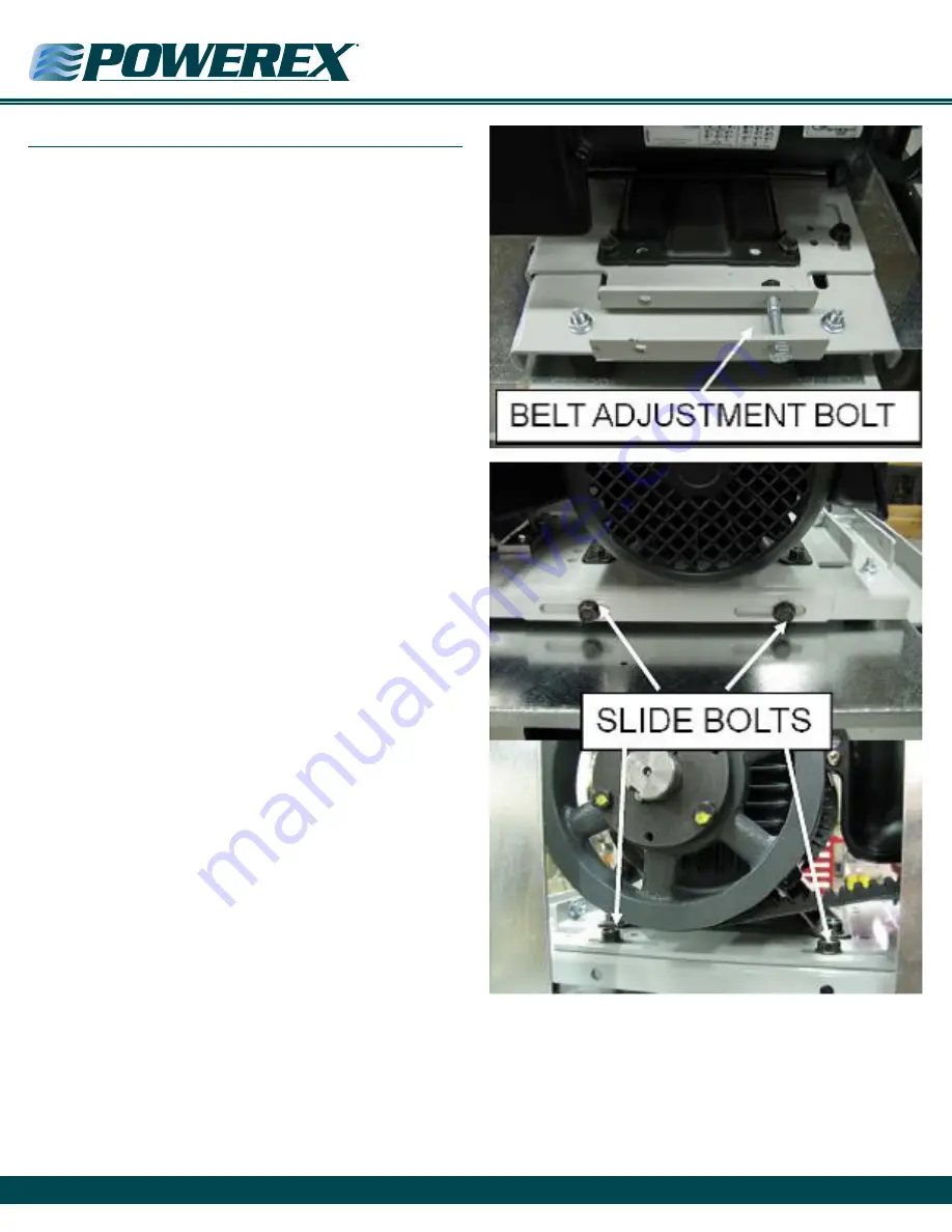
Using the Motor Slide Base to Tension the Belts
Belt tension is set at the factory. If slippage is detected, reset the
tensions as follows:
After the first 200 to 500 running hours or at any time chirping is
heard on startup, check the belt tension. If tension is below 25 pounds
on any belt, increase the center distance using the motor slide base
so that belt tension is 45 to 50 pounds. The motor slide base details
are shown below. If installing new belts see the procedure below.


