6
©
All rights reserved. All trademarks are property of their respective owners.
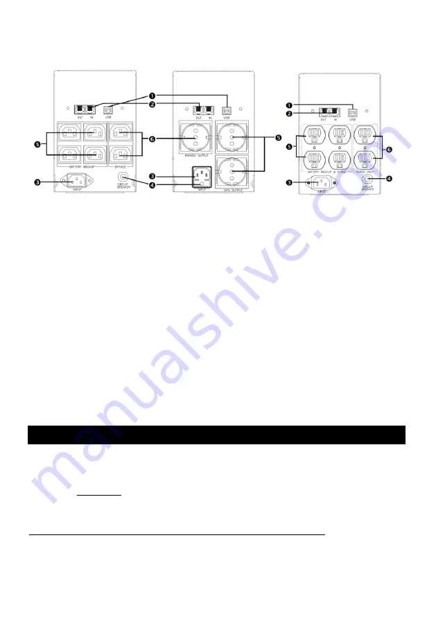
4.4 Rear panel view
Rear Panel
REMOTE PORT
Provide USB to support NOVELL, LINIX, UNIX, WINDOWS and other operating systems.
TEL/ MODEM protection
T e l e c o m t r a n s f e r p o r t s p r o v i d e u s e r s t o e xt e n d t h e a p p l i c a t i o n s .
Caution:
To reduce the risk of fire, use only No. 26AWG or larger telecommunication line cord.
AC INPUT POWER RECEPTACLE
The input power cord needs to connect the rear inlet socket of the UPS and plug into a socket on
the wall. Please notice the voltage of utility power should match with the UPS. For example, the
rating voltage of UPS is 110V/(220V), the input utility power should be the same as 110V/(220V).
INPUT CIRCUIT BREAKER/ FUSE
It trips when the connected loads exceed the protected receptacle‘s capacity.
UPS & SURGE PROTECTED OUTLETS
When utility power is normal, the UPS outlets are powered by utility power with AVR function.
Any higher or lower utility power would be rectified by AVR function. When utility power is fail,
the UPS outlets are powered from battery.
CONVENIENCE OUTLET(S)
CONVENIENCE outlets protect the loads from spike.
5.
UPS Monitoring Connection
To monitor the UPS status and perform some simple UPS self-test, it is required to connect the
UPS to the computer or the internet.
5.1 Connect UPS to Computer with USB / RS232 port
Refer to Chapter 4.4, find the USB / RS232 port at the rear of UPS.
Connect UPS and Computer with the communication cable provided with UPS.
Make sure the computer supports the power management software and install the power
management software in the Computer.
!!Notice!!
Either USB port or RS232 port, only one port will function at a time.


