background image

6.9.3 Change Engine Oil

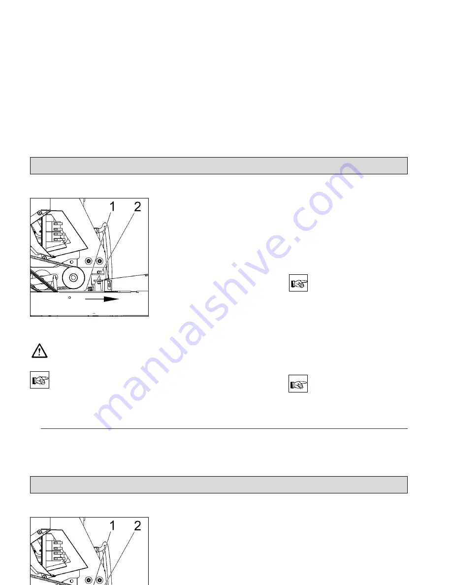
Engine oil changing, right side 

of machine

Caution!

Burning hazard at muffler

pipe! 

If the machine has not been

used for a longer time, let

the engine run to have the

oil attained appropriate tem-

perature.

Proceed to the following befor

changing engine oil:

-  Turn engine off and pull key.

-  Secure machine by engaging par-

king brake.

-  Open seat hood.

-  Loosen quick-release locks (Fig.

20/1).

-  Remove cover, filter case (Fig.

20/2).

-  Loosen screws at the inside of the

right lateral fairing and remove.

-  Lightly tilt lateral fairing to the outsi-

de then remove by pulling up.

-  Remove drain hose (Fig. 24/1) from

holding clamp (Fig. 24/2) and lead it

downwards through the vehicle fra-

me.

-  Loosen clamp, pull drain plug from

the hose and drain oil.

-  Close drain hose (Fig. 24/1) by plug

and protect with clamp.

-  Fasten drain hose (Fig. 24/1) at hol-

ding clamp.

-  Fill engine oil into check opening

with the machine standing on level

ground.

-  Check oil level with dipstick, conti-

nue filling if required

Engine oil: SAE 15 W-40

Filling: approx. 1.1 litre

Use an oil-resistant funnel

for filling engine oil.

6.9.4 Air Cleaner

The air cleaner is located in the engi-
ne's compartment. Clean the foam-
type filter after every 50 hours of ope-
ration and the paper insert after every
100 hours of operation.

Proceed to daily cleaning of

the air cleaner with heavy

dust formation.

48

Maintenance/Service

Fig.24

Direction of travel

Summary of Contents for apex 47 g

Page 1: ...Instruction Manual Apex 47 G GH 6502 34 54...

Page 2: ...s manual identifies items relevant to safety Please observe the safety provisions see chapter 1 Before first operation of the machine read these instructions and safety in formation carefully and comp...

Page 3: ...ised PowerBoss an service center and confir med in the Maintenance certificate which is the warranty document The following is excluded from warran ty fuses natural wear damages caused by overload ine...

Page 4: ...10 1 Check hydraulic Fluid Level 50 6 10 2 Refill Hydraulic fluid 50 6 10 3 Change Hydraulic Fluid Filter 50 6 10 4 Check and Refill Hydraulic System Lifted Up Disposal 51 2 7 2 Apex 47 GH 17 2 8 Brak...

Page 5: ...an V Belt 53 6 11 4 Replace Hydraulic Pump V Belt 54 6 12 Electric System 55 6 13 Maintenance System 57 Contents 5 6 11 V Belt Drive 52 6 11 1 Replace Cylinder Broom V Belt 53 6 11 2 Replace Side Brus...

Page 6: ...about safe operation Illegible or lost labels have to be repla ced Make sure that all covers are fitted before starting to sweep Provide for sufficient ventilation when sweeping indoors dust and comb...

Page 7: ...imprecise or non observance of instructions or prescribed work routine important information on handling the Apex 47 in order to maintain operability due to use of substances representing an inherent...

Page 8: ...Read and observe operator s Manual 5 Ignition lock 6 Brake 7 Noise performance 8 91 dB A Apex 47 G 91 dB A Apex 47 GH Safety Information Fig 1 1 3 Labels at the Machine The following safety and infor...

Page 9: ...gns Hydraulic fluid 9 Rotating parts 10 Burning surface 11 Cylinder broom wearing take up 12 Vehicle identification number 13 Safety Information 1 3 Labels at the Machine Hydraulic fluid 9 Rotating pa...

Page 10: ...an by means of high pressure cleaner or vapour jet Apex 47 type name 15 Pinching hazard 16 with the Apex GH only Safety Information 1 3 Labels at the Machine High pressure cleaner 14 Safety Informatio...

Page 11: ...he machine running This machine must not be used as dust evacuating machine with dust filter in sert separator to collect dusts which are hazardous to health Compared to four wheeled vehicles driving...

Page 12: ...clean the Apex 47 by means of high pressure cle aner or vapour jet Proceed to cleaning of the dirt hopper in regular inter vals to preclude formation of bacterial deposits Safety Information Warning a...

Page 13: ...use of other cylinder brooms and side brushes may affect your safety When handling lubri cating agents the ap plicable regulations for protection of the envi ronment and preven tion of fire have to be...

Page 14: ...vel wear safety glas ses If acid splashes get in to the eyes rinse with clear water for 15 minutes and contact a doctor imm ediately Use appropriate protective means e g protective glo ves or finger s...

Page 15: ...well the applicable provisions for Safety and Health at W ork and the Fire Regulations internal safety provisions Safety Information 1 7 Accident Prevention Regulations BGV D 29 Vehicles According to...

Page 16: ...res which are to be emptied manually Dirt disposal at the Apex 47 GH is rea lized via lift up disposal lift up height 1350mm directly into standard waste containers 2 1 2 Apex 47 GH Principle of Apex...

Page 17: ...on the set dust partly falls off into the dirt hoper To ensure working in a dust free ambiance however actuate the shaking system regularly or after request by the pilot lamp at the latest 2 6 Steerin...

Page 18: ...The hydraulic system comprises a compact unit hydraulic pump with hydraulic tank the hydraulic hoses and a hydraulic cylinder Hydraulic fluid Mobiloil DTE 15 M The named hydraulic fluid has been fille...

Page 19: ...fuel oil only Store fuel in approved and closed reservoirs only Turn engine off Secure machine by engaging the parking brake Pull ignition key Fold back seat hood Fuel tank Check filling level at the...

Page 20: ...switch and lights simul taneously in case of insufficient oil level Before the machine is ope rable again refill oil until the prescribed level is attai ned low oil level switch Use clean oil only fo...

Page 21: ...ntrol panel 7 Seat adjustment 8 Safety knob lock for release of swinging dirt hopper function Apex 47 GH 9 Release lever for swinging dirt hopper function Apex 47 GH Operation Fig 6 4 Operation 4 1 Ap...

Page 22: ...ts required for operation Adjust seat lengthwise push lever slightly to the right and displace seat forwards or backwards to the requi red position Then let the lever catch again 8 Safety knob lock fo...

Page 23: ...Side brush lever 10 Pilot lamp parking brake 11 Battery charge status indicator 12 Hourmeter 13 Pilot lamp fan 14 Pilot lamp shaking system 15 Engine speed regulation knob 16 Ignition switch Operation...

Page 24: ...before pressing the key for lifting lowering lifted up dis posal function Hold the key during lifting lowering Before changing lifting to lo wering or vice versa the Release Lifted Up Dispo sal key h...

Page 25: ...ervals After jolting the knob is to be kept in position 1 for ab out 10 seconds Reduce engine speed to id ling in order to optimize the cleaning result in case of heavy fine dust load or stop the engi...

Page 26: ...parking brake Extinguishes upon release of the parking brake 11 Battery charge status indicator red lights upon actuation of the ignition switch and has to extinguish as the engine fires 12 Hourmeter...

Page 27: ...thorised use For safety reasons the Apex 47 has been equipped with a seat contact switch Starting the engine is possi ble only after the driver has taken place on the seat If seat contact is interrupt...

Page 28: ...pex 47 GH Lift side brush and cylinder broom before emptying of the dirt hoppers If the hopper is lifted with the cylinder broom still run ning the engine is switched off Emptying dirt hopper 1 Lift o...

Page 29: ...is released Actuate switch Fig 10 2 by pushing lift dirt hopper Dirt hopper Fig 9 3 is lifted out Back the Apex 47 GH until the dirt hopper is positioned above the container for disposal Pull the saf...

Page 30: ...ng dirt hopper 1 Safety knob 2 Release lever swing dirt hopper If the cylinder broom is swit ched on with the dirt hopper being lifted the engine stops Should the dirt hopper not be completely emptied...

Page 31: ...reasons the Apex 47 is equipped with a seat contact switch Starting the engine is possible only when the driver is seated Switch all levers and switches to neutral position Actuate parking brake Actua...

Page 32: ...ine slows down to standstill Actuate parking brake Lift side brush and cylinder broom Turn engine off Slowing down the Apex 47 is possible by applying oppo site forces with the drive pe dal or by usin...

Page 33: ...ticlockwise approx a quarter turn against the stop 4 5 7 Transport Before transporting the Apex 47 on other vehicles engage the parking brake and secure the machine by straps and by placing wedges at...

Page 34: ...Gradability max mm mm mm mm mm kg kg km h km h km h mm mm m h m h 1520 1000 1120 1240 1300 480 680 6 0 4 0 6 0 700 970 1240 5800 7450 4200 16 1520 1000 1120 1240 1300 410 580 6 0 4 0 6 0 700 970 1240...

Page 35: ...ed Serial bristling Dirt hopper Hopper capacity m piece mm mm 1 min mm mm mm 1 min liter 2 8 1 700 345 290 530 20 50 10 12 v shaped PA 1 1 4 460 90 PA 70 2 8 1 700 345 290 530 20 50 10 12 v shaped PA...

Page 36: ...ilter Kawasaki bar cm KW 1 min liter liter h Type liter 4 00 4 6PR 6 Option Kawasaki FE 250 D 4 cycle 1 cyl 249 6 2475 25 5 3 1 2 15W 40 1 1 NGK BP 5 ES 11013 2128 11013 2129 4 00 4 6PR 6 Option Kawas...

Page 37: ...Ah A DTE 15 M or an equivalent oil 10 CS 050 P 10 A DTE 15 M or an equivalent oil 0 76 12 45 13 DTE 15 M or an equivalent oil 10 CS 050 P 10 A 12 45 13 Technical Data Apex 47 Apex 47 G Apex 47 GH Hyd...

Page 38: ...er normal working condi tions The frequency weighted acceleration measured according to EN 1032 which have an effect upon the lower limbs feet and seat amounts under normal working conditions dB A dB...

Page 39: ...meplate Refer to chapter 1 3 1 Fig 2 13 for position of nameplate Collect spilled oil and provide for adequate disposal Use appropriate tools for servicing maintenance and adjusting work only Spare pa...

Page 40: ...djust Sweeping Track An adjustment device allows adapta tion to different sweeping conditions The cylinder broom has to be adjusted for normal use and with regard to a low degree of wearing as describ...

Page 41: ...sen handle Fig 16 3 Turn star shaped knob Fig 16 1 to the left wider sweeping track to the right smaller sweeping track Fix handle Fig 16 3 Broom adjustment sticker Fig 16 2 With one full turn of the...

Page 42: ...th the floor 6 5 Folding Apron Adjustment Adjust folding apron Turn engine off and pull key Secure machine by engaging par king brake Remove cover as described in the paragraph Mount Dismount Cylin de...

Page 43: ...Replace side brush Turn engine off and pull key Secure machine by engaging parking brake Disconnect battery plug Side brush lifted Loosen hexagonal nut Fig 19 1 und remove together with washer Remove...

Page 44: ...o motor Fig 21 3 Hook frame at indicated position Fig 21 4 Remove plate filter Fig 21 5 For mounting of plate filter proceed in inverse order Dismount plate filter 1 Quick release locks 2 Cover of fil...

Page 45: ...Plate filter 1 Detent hook 2 Wing screws 3 Frame with electro motor 4 Opening for detent lever 5 Plate filter 45 Maintenance Service Fig 21 Maintenance Service...

Page 46: ...side of the filter points to the bottom Basic cleaning of plate filter 1 Plate filter Maintenance Service Fig 22 Clearance approx 1 m Soiled side Floor 6 8 Basic Cleaning of Plate Filter Hold the plat...

Page 47: ...d pull key Secure machine by engaging par king brake Open seat hood Pull plug Fig 23 1 with dipstick Wipe dipstick push it into opening until stop and pull it again Oil level has to mark between mini...

Page 48: ...p Fill engine oil into check opening with the machine standing on level ground Check oil level with dipstick conti nue filling if required Engine oil SAE 15 W 40 Filling approx 1 1 litre Use an oil re...

Page 49: ...oil and fil ters are concerned by maintenance work only Premature failure can be prevented by regular inspection and periodical main tenance see maintenance schedule page 57 and following We recommend...

Page 50: ...rder to guarantee fluid supply of the travel drive assem bly even if the fluid filter is soiled Change the fluid filter after the first 100 hours of operation Turn hydraulic fluid filter Fig 27 2 coun...

Page 51: ...the minimum Fig 28 2 It should read between the minimum Fig 28 2 and the ma ximum Fig 28 3 Refill hydraulic fluid Remove lid Fig 28 4 and refill as required Close lid of hydraulic fluid tank Use Mobil...

Page 52: ...room V belt 14 Cylinder broom belt pulley 15 Tension spring 16 Tensioning roller lever 17 Tension spring 18 Tensioning roller lever for hydraulic pump V belt 19 Tensioning roller lever for cylinder br...

Page 53: ...pen seat hood Loosen hexagon nuts Fig 29 6 and remove together with belt guide Fig 29 5 Detent V belt Fig 29 7 with tensio ning roller lever Fig 29 19 and ta ke from the belt pulley Loosen tensioning...

Page 54: ...lt pulley Loosen tensioning roller Fig 29 2 and detent the V belt and then re move Unhinge tension spring Fig 29 17 Remove V belt Fig 29 4 Proceed in inverse order for mounting Maintenance Service 6 1...

Page 55: ...option 10A 9 F11 Shaking motor 30A 10 F12 Generator charge status indicator 5A 11 F14 Flashlight option 5A 12 LPG option control unit 13 K6 Relay lifted up disposal 14 K7 Relay lifted up disposal 15...

Page 56: ...lay impulse relay shaking 22 F13 Hydraulic unit for lifted up disposal 30A 56 Maintenance Service Fig 30 Electric System continued 16 K9 Relay lifted up disposal 17 K10 Relay lift hopper 18 K11 Relay...

Page 57: ...nlet 0 15mm outlet each in cold state X Check starter battery acid level and top with distilled water if required clean and grease battery terminals X Change hydraulic fluid filter and refill fluid us...

Page 58: ...ristles for wearing adjust if required or replace side brush X Visual check of V belts X Check V belt for wearing and correct tension and re adjust if required 5 X Check service parking brake and re a...

Page 59: ...and adjust tension if required X 6 13 Maintenance Schedule hours of operation 59 Maintenance Service Daily after first every 100 every 200 every 500 Check hydraulic fluid level of lifted up disposal...

Page 60: ...amp carried out on __________ at __________ operating hours 900 operating hours Maintenance Workshop stamp carried out on __________ at __________ operating hours 1000 operating hours Maintenance Work...

Page 61: ...S A and Canada should contact their local distributor for export warranty policies PowerBoss is not responsible for costs or repairs performed by persons other than those specifically authorized byPo...

Page 62: ...ers one year parts one year labor ninety days travel Not to exceed two hours Replacement parts Ninety days Batteries 0 3 months replacement 4 12 months pro rate Polypropyl Plastic Tanks Ten years no a...

Page 63: ......

Page 64: ...Excellencs Meets clean Excellencs Meets clean PowerBoss Inc 175 Anderson Street Aberdeen NC 28315 U S A Telephone 910 944 2105 Fax 910 944 740 88 10 2787...

Reviews: