Page 9
Good Ground
Corrosion
O T
H
H
P A
S OT
S S
O T
H
H
F A
S OT
I L
Press &
hold Hot
Shot
®
Press &
hold Hot
Shot
®
IV
Continued
H
O M
1
H
0 0
Hot Shot
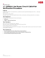
e) Dual Meter Feature:
The Dual Meter feature is available only in Power Probe HOOK
Mode. When diagnosing chassis grounds it is possible to have
voltage drops caused by systems within the vehicle operating
when the key is off. It can take several minutes for the systems
to shut down. If you are turning the key on and off for diagnosing
purposes, it can be difficult to get accurate resistance readings
due to the voltage drops. Typically ohmmeters will give you a
reading that is skewed by these voltage drops and if you are
unaware they are there, you could spend time fixing problems
that don’t exist.
If there are millivolts present on a chassis ground the Power
Probe HOOK will display a unique feature we call Dual Meter.
You will get a resistance reading on the bottom of the screen
and a millivolt reading on the top of the screen at the same
time. The ohm reading displayed when this feature is active will
have a coarse correction factor intended to improve accuracy.
In Power Probe HOOK mode, this feature will automatically
display when the voltage on ground is between .002 and .200
millivolts and ohms is less than 250. If the voltage drops below
.002 volts, normal ohmmeter will display. If there is between
.002 and .200 volts present and the ohms exceed 250, normal
ohmmeter will display. Above 250 ohms, millivolts will have no
affect on the ohm reading. If the voltage exceeds .200 volts,
M
A P
0
2
0
5
5
1
H
O M 2
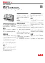
d) Hot Shot
®
Testing in Power Probe
Hook Mode:
Hot Shot
®
is available at all source voltages from 12 to 48. The
rule of thumb is that when the Hot shot feature is available,
you can verify the resistance of that circuit is > or < 1 ohm. If
you get a pass result you know the resistance is < 1 ohm and
you have a good power feed connection. A fail result indicates
>1 ohm. For reference, the source voltage does affect the out-
come of the pass result. All pass results reflect less than 1
ohm but there is a value difference depending on the source
voltage. Pass at 12V = <.2 ohms, 24V = <.4 ohms, 36V = <.6
ohms, 48V = <.8 ohms. All are less than 1 ohm, but under-
standing this may help in your diagnosis.
WARNING: HOT SHOT
®
is only designed for supply powers
and grounds. HOT SHOT
®
should never be used on any sensi-
tive electronics such as modules, sensors etc.
NEVER: Perform any tests on any SRS system without the
system being completely disabled, modules unplugged and
simulators installed in place of all pyrotechnics. Doing so can
lead to injury do to unwanted deployment and permanent mod-
ule damage.
WARNING: When working on computer grounds or any oth-
er sensitive circuits, HOT SHOT
®
should not be used. The
components need to be unplugged (modules, relays, sensors,
switches, etc.) Now HOT SHOT
®
can be used to load the wiring
not the component. This is the true method that HOT SHOT
®
is
intended for, the wiring not the components.