Voltage
Number
Rating
(1)
Peak Inrush
Current, mA(2)
Nominal RMS
Current, mA
SPST480
480 Vac
375
21
SPST600
600 Vac
300
17
SPSTL480 480 Vac
750
20
SPSTL600 600 Vac
600
16
(1)
Rated for 50/60 Hz. Rating is 120 Vac without
step-down transformer.
Peak inrush current is present for 2-6 ms after activation. This
number is provided so that fuses and supplies can be chosen
appropriately.
(2)
—
Table 1. Catalog numbers and voltages for the Shunt Trip and Shunt Trip with Lockout
Voltage
Peak Inrush
Accessory
Rating
Current, A
Nominal RMS
Current, mA
Shunt Trip
120 Vac
1.5
85
Shunt Trip/
120 Vac
3
80
Lockout
—
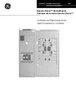
Figure 1. Shunt Trip with Lockout
1
AVERTISSEMENT:
Les modules de d
é
clenchement shunt
480 Vac et 600 Vac doivent
ê
tre utilis
é
s avec le
transformateur abaisseur de tension qui est fourni.
AVERTISSEMENT:
Avant d'installer
tout accessoire, mettre
le disjoncteur en position OFF, le d
é
connecter de
toute tension
d'alimentation,
et
d
é
charger
l
es
ressorts d'armement.
WARNING:
Before installing any accessories, turn the
breaker OFF, disconnect it from all voltage sources, and
discharge the charging springs.
The Shunt Trip or Shunt Trip with Lockout will cause the
circuit breaker to trip when the control voltage is greater
than 55% of the rated ac value. Control power to the Shunt
Trip must be removed before the breaker can be closed.
Control power to the Shunt Trip with Lockout must be
removed for a minimum of 0.25 second before the breaker
can be closed.
Catalog
—
Table 2 Voltage and current ratings for the 120 Vac Shunt Trip and Shunt Trip with
Lockout.
Installation
The Shunt Trip and Shunt Trip with Lockout accessories,
shown in Figure1, can be installed in 800-4000 ampere frame
Power Break® II circuit breakers. These accessories allow the
breaker to be tripped electrically from a remote location.
In addition to providing a trip signal to the breaker, the Shunt
Trip accessories can be set up to interact with other Power
Break II accessories, when used with a MicroVersaTrip Plus or
MicroVersaTripPM Trip Unit. DIP switches on the rear of the
breaker Trip Unit can configure the Shunt Trip accessories to
activate a Bell Alarm-Alarm Only accessory or a Bell Alarm
with Lock out accessory when a shunt trip occurs. The
Accessory Configuration section below describes how this can
be done. If the breaker is equipped with a Power+Trip Unit, it
is configured so that only protection trips will activate a Bell
Alarm
Alarm Only or Bell Alarm with Lockout.
The catalog numbers for the Shunt Trip and Shunt Trip with
Lockout for 480 and 600Vac are listed in Table 1. Voltage and
current ratings in Table1 are given at the input of the
transformer. The voltage and current ratings of the input to
the accessory are equal to that of the 120Vac version of the
accessory. Table 2 Iists these ratings.
GEH
6519
INSTRUCTIONS
Power Break® II Circuit Breaker Accessories
Shunt Trip and Shunt Trip with Lockout 480& 600Vac
Introduction
Operation
Apply control voltage to the primary of the supplied step-
down transformer. The secondary of the transformer is
connected to terminals 31 and 32 of the terminal strip on the
right side of the breaker.
WARNING: 480 Vac and 600 Vac Shunt Trip accessories
must be used with the supplied step-down transformer