Power-Flo Pumps & Systems • 877-24PUMPS • www.powerfl opumps.com
12
Outer Seal (Single & Double) -
Handle
seal parts with care. Remove c-clip (43),
seal (33) spring and rotating member
from shaft. Examine all seal parts. Inspect
contact faces for signs of uneven wear
tracks on stationary, chips and scratches
on either seal face.
DO NOT interchange
seal components, replace the entire
shaft seal (33).
Seal Plate (Double) -
Remove cap screws
(52) and washers (11) from seal plate (51).
Remove seal plate (51) and square ring
(24) from intermediate coupling (21B).
With fl at screwdriver, press out seal (33)
stationary member. Inspect square ring
(24) for cuts or abrasions.
Checking Capacitors -
Loosen gland
nut (3) and remove cap screws (22) and
washers (11) from upper housing (19).
Check motor capacitors (14) & (16) with
an Ohm meter by placing a screwdriver
across both terminals and to ground the
capacitor then remove. Connect Ohm
meter, set on high scale to terminals. If
needle moves to infi nity (∞) then drifts
back, the capacitor is good. If needle does
not move or moves to infi nity (∞) and
does not drift back, replace the capacitor.
Motor -
Remove wires from terminal
block (37) and remove cable assembly
(3) and upper housing (19). Remove
pipe plug (4) from housing (15) and
drain oil if not already done so. Position
pump upright using blocks or pvc pipe
to avoid resting pump on the shaft.
Remove retaining ring (38). Using a 1/4-20
bolt, thread bolt into the center of the
terminal block (37) and pull straight up to
removing it and o-ring (12). Disconnect all
wires, noting where each was connected.
There are numbers next to the pins on the
bottom of block, use these for reference.
Remove cap screws (35) and lockwashers
(11) from motor housing (15). Vertically
lift motor housing (15) from intermediate
coupling (21) along with square ring (20),
replace if cut or damaged. Remove stator
bolts and carefully remove stator housing
from rotor. Pull rotor out with bearing (18).
Inspect motor winding for shorts and
check resistance values. Check rotor for
wear. If rotor or the stator windings are
defective, the complete motor must be
replaced.
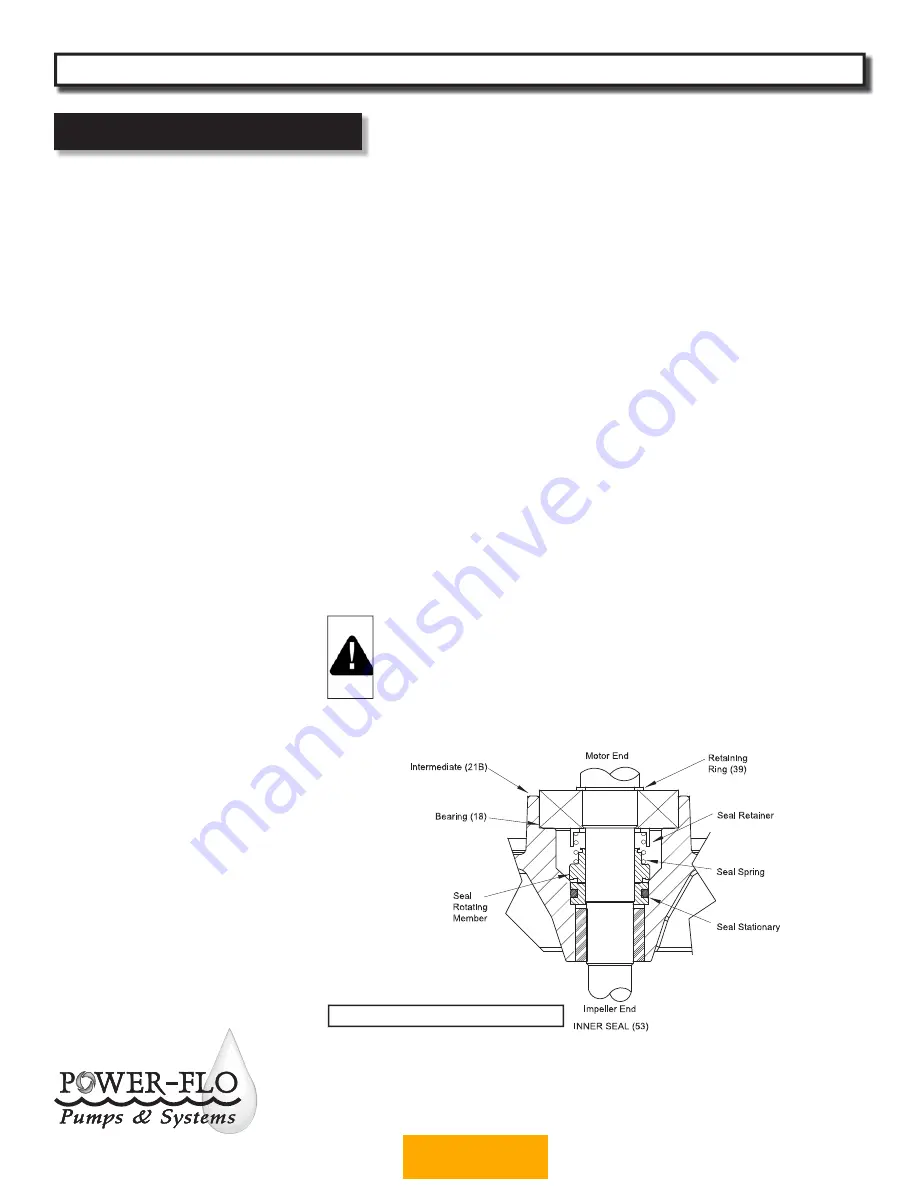
Inner Seal (Double) -
Remove seal (53)
rotating member and spring from rotor
shaft. Press stationary from intermediate
(21B) with fl at screwdriver. Examine all
seal parts. Inspect contact faces for signs
of uneven wear tracks on stationary,
chips and scratches on either seal face.
DO NOT interchange seal components,
replace the entire shaft seal (53).
Bearings -
Remove retaining ring (39)
from shaft. Using a wheel puller or arbor
press remove bearing (18) from shaft.
Remove upper motor bearing from shaft
with a bearing puller. (See Figure 5).
On Double Seal Units
, Check sleeve
bearing (23) for excessive wear, if
replacement is required, press sleeve from
intermediate coupling (21).
IMPORTANT! - All parts must be
clean before reassembly.
Handle seal parts with extreme
care. DO NOT damage lapped
surfaces.
Reassembly
Bearing -
Be careful not to damage the
rotor shaft when replacing bearing. Using
an arbor press, hold the rotor and press
the upper bearing on the rotor shaft,
applying force to the inner race of the
bearing only. Replace upper retaing ring
onto rotor shaft. In the same manner
replace lower bearing (18) onto rotor
shaft. Place lower retaining ring (39) onto
shaft.
Inner Seal (Double) -
Clean and oil seal
cavity in intermediate coupling (21B).
Lightly oil
(Do not use grease)
outer
surface of stationary member. Press
seal’s (53) stationary member firmly into
intermediate coupling (21B), using a seal
tool or pipe. Nothing should come in
contact with the seal face except the seal
tool. Be sure the stationary is in straight.
Place seal’s (53) retaining ring and spring
over shaft until seated on shaft shoulder.
Slide a bullet tool over rotor shaft
threads.
Lightly oil
(Do not use grease)
shaft,
bullet, and inner surface of bellows on
rotating member, with fi nished end away
from motor, slide rotating member over
bullet and onto shaft until it engages
spring. Make sure spring is seated in
retaining ring and spring is lined up on
rotating member and not cocked or
resting on bellows tail. (See Figure 5)
Service
PFGPC - 2HP
Submersible Grinder Pumps
Figure 5 (Double Seal Unit Shown)
BACK TO INDEX


