background image

Power-Flo Pumps & Systems • 877-24PUMPS • www.powerfl opumps.com

12

Power Cable Connection - 

Check power 

cord (3) for cracks or damage and replace 
if required. Insert female end of cord 
plug into housing bore 

aligning timing 

mark

 with hole in terminal block (37) 

see Figure (5). Compress cord plug with 
compression flange by tightening cap 
screws (1) with lock washers (2) into the 
housing (15). Torque to 132 in-lbs.

Seal Plate -

 Lubricate and set square 

ring (24) in bottom groove of seal plate 
(31). Place seal plate (31) over shaft and 
onto intermediate coupling (21), being 
sure square ring (24) is not twisted and 
in the groove. Place two capscrews (32) 
with lockwashers (11) into seal plate and 
torque to 6.5 ft/lbs.

Outer Seal - 

Clean and oil stationary

seal cavity in seal plate (31). Slide seal 
guide tool over motor shaft. Lightly 
oil 

(Do not use grease)

 outer surface 

of seal’s (33) stationary member. Press 
stationary fi rmly into seal plate (31) using 
a seal pusher tool. Be sure the stationary 
member is in straight. Nothing but the 
seal tool is to come in contact with seal 
face. (See Figure 6)

 IMPORTANT ! Do not hammer 
 on the seal pusher. It will 
 damage the seal face.

With seal guide tool over motor shaft, 
Lightly oil 

(Do not use grease)

 guide, 

shaft and inner surface of bellows on 
rotating seal. With lapped surface of 
rotating member facing inward toward 
stationary, slide rotating member over 
guide and onto shaft, using seal pusher 
tool, until lapped faces of stationary and 
rotating seal are together. Place spring 
over shaft and rotating member. 

Be sure it is seated on the retainer and 
not cocked or resting on bellows tail.

Impeller - 

Place impeller (30) on motor 

shaft, with machined step fi tting inside 
the inside diameter of seal spring, by 
turning clockwise while holding shaft 
stationary with screwdriver.

Shredding Ring -

 Install shredding ring 

(27) into volute with the use of an arbor 
press.

Volute -

 Place volute (25) on seal plate 

(31). Place nuts (41) with lockwashers 
(11) onto studs (34) and torque evenly to 
11 ft/lbs.

Note: Discharge must line up with notch 
in motor housing.

Cutter -

 Screw radial cutter (29) onto 

shaft, turning it clockwise while holding 
the shaft stationary with a screwdriver. 
The radial cutter (29) should be fl ush with 
shredding ring (27), on suction side to 
within ± .020. Place washer (28) on screw 
(40), apply green Loctite on threads and 
place into shaft and tighten.

Figure 5

Service

Figure 6

PFG - HH & HV 2HP 


        Submersible Grinder Pumps

Figure 4

BACK TO INDEX

Summary of Contents for PFG2002HH

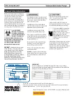
Page 1: ...ISP No PFGrinder 9 09 INSTALLATION SERVICE PARTS MANUAL Power Flo Pumps Systems 877 24PUMPS www powerflopumps com Series PFG2002HV HH PFG2022HV HH PFG2062HV HH PFG2032HV HH PFG2042HV HH Double Seal 2...

Page 2: ...ood Shells Aquarium Gravel Cat Litter Plastic Objects toys utensils etc Sanitary Napkins or Tampons Diapers Rags Disposable Wipes or Cloth Medications Flammable Material Oil or Grease Strong Chemicals...

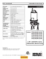
Page 3: ...AFT Stainless Steel SQUARE RINGS Buna N HARDWARE Stainless Steel PAINT Powder Coated Industrial Grade SEAL Tandem Double Mechanical Carbon Ceramic Buna N UPPER BEARING Single row Ball Oil Lubricated I...

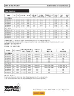
Page 4: ...vailable if a Power Flo control panel is not used See page 13 for wiring schematic PF88243 for 200 volt 1 phase PF73306 for 230 volt 1 phase Specifications MODEL HP Volts Ph BREAKER SIZE HEATER SIZE V...

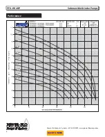
Page 5: ...Power Flo Pumps Systems 877 24PUMPS www powerflopumps com 5 Performance PFG HH 2HP Submersible Grinder Pumps BACK TO INDEX...

Page 6: ...Power Flo Pumps Systems 877 24PUMPS www powerflopumps com 6 Performance PFG HV 2HP Submersible Grinder Pumps BACK TO INDEX...

Page 7: ...not pump out of liquid Controls PFG series grinders require a separate approved pump control device or panel for automatic operation Be sure the electrical specification of the control selected proper...

Page 8: ...tential problems can be corrected It is recommended that the level control float should be set to insure that the liquid in the sump never drops below the top of the motor housing or a minimum level o...

Page 9: ...ashlight visually inspect the oil in the housing 15 to make sure it is clean and clear light amber in color and free from suspended particles Milky white oil indicates the presence of water Oil level...

Page 10: ...ounter clockwise to remove CAUTION Cutter edges are very SHARP Cutter must be removed before removing volute Volute Remove hex nuts 41 from studs 34 and remove volute 25 from pump Shredding Ring To re...

Page 11: ...g should come in contact with the seal face except the seal tool Be sure the stationary is in straight Place seal s 19 retaining ring and spring over shaft until seated on shaft shoulder Slide a bulle...

Page 12: ...mage the seal face With seal guide tool over motor shaft Lightly oil Do not use grease guide shaft and inner surface of bellows on rotating seal With lapped surface of rotating member facing inward to...

Page 13: ...Figure 7 200 240 Volt 3Phase Figure 7 460 Volt 3Phase Figure 7 200 230 Volt 1Phase Pump Wiring Schematics PFG HH HV 2HP Submersible Grinder Pumps 1Phase Capacitor Relay Pack For Control Panels 2HP 20...

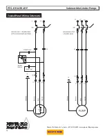
Page 14: ...Power Flo Pumps Systems 877 24PUMPS www powerflopumps com 14 Typical Panel Wiring Schematic PFG HH HV 2HP Submersible Grinder Pumps BACK TO INDEX...

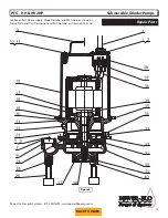
Page 15: ...w powerflopumps com 15 Figure 8 Repair Parts For Repair Part Please supply Model Number and MFG Date as shown on Name Plate and Part Description and Part Number as shown on Parts List PFG HH HV 2HP Su...

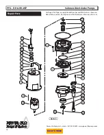
Page 16: ...w powerflopumps com 16 Figure 9 PFG HH HV 2HP Submersible Grinder Pumps Repair Parts For Repair Part Please supply Model Number and MFG Date as shown on Name Plate and Part Description and Part Number...

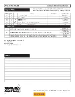
Page 17: ...Seal Carbon Ceramic Buna N PF111131 20 1 6 Square Ring PF074498 21 1 Bearing Bracket PF108879 22 1 Pipe Plug 1 4 NPT 23 1 Bronze Insert 24 1 6 Square Ring PF067564 25 1 Volute PF108344 26 3 Pump Leg...

Page 18: ...6 Retaining Ring PF061143 40 1 6 Impeller Screw 1 4 20 x 3 4 Lg Stainless PF070704 41 4 Hex Nut 5 16 18 Stainless Repair Kits CUTTER KIT Includes Item numbers 27 28 29 40 PFG2HV CT PFG2HH CT 6 OVERHAU...

Page 19: ...uired Consult the factory Disconnect unit electrically Remove the pump from the basin Detach the pump base and clean the area around the impeller Rotate impeller by hand Reassemble and reinstall Pump...

Page 20: ...ned in accordance with Manufacturer s installation instructions that has been exposed to outside substances including but not limited to the following sand gravel cement mud tar hydrocarbons hydrocarb...

Reviews: