


- 18 -
1500_GB-EINSATZ_2719
OPERATION
GB
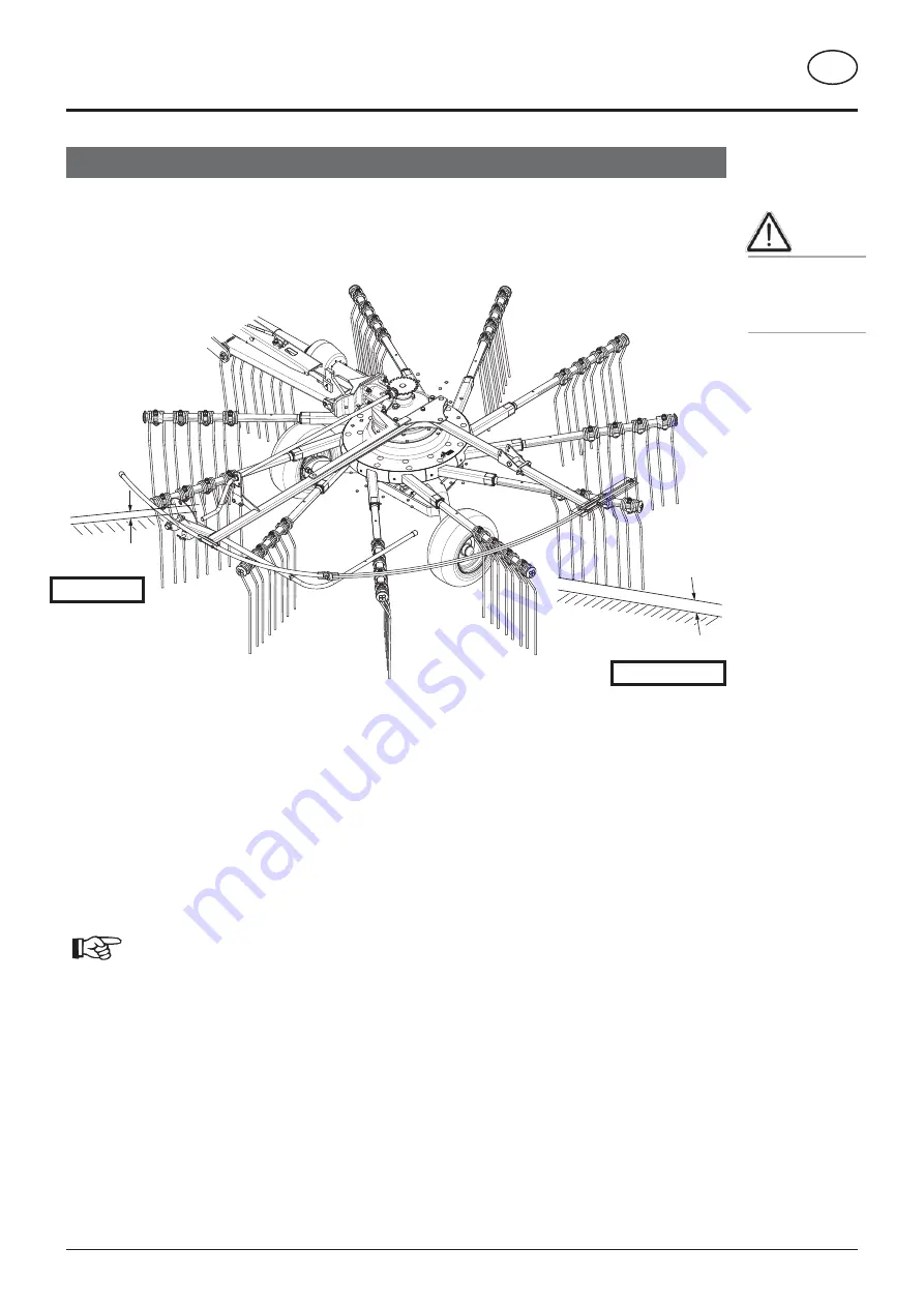
3,5 cm
2,0 cm
482-15-15
Rake start
Rake end
Example - left rotor with tandem chassis:
Requirement:
- Level and solid ground
- 1.5 bar pressure in all tyres
- The machine is attached to the tractor and in the working position
1. Step:
Lower the tines using crank. The lowest tines should no
longer sweep the ground when the rotor is turned.
2. Step:
Set the cross gradient using eccentric bolts in the
"Rake start" position so that the first tines activat-
ed (rake start) have a ground clearance of approx.
1 - 1.5 cm.
Note: Set both eccentric bolts simultane-
ously on the relevant side.
3. Step:
Setting the rake height using crank handle. The ground
clearance in the "rake start" position should now be approx.
3.5 cm. The ground clearance in the "rake end" position
should now be approx. 2.0 cm.
3. Step
3. Step
Be advised!
Operating the
machine without
inner feeler wheel
is prohibited!


