PNA-3303 User’s Manual
9
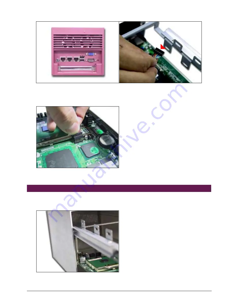
8. Fix the two screws on the back of PNA-3303 (
Fig. 2-30
)
Fig. 2-30
Take off the VGA outlet cover
Fig. 2-31
The triangle sign
9. Connect the V-100 connector to PPAP-200. The triangle sign (
Fig. 2-30
) on the connector
indicates the position where pin 2 should be connected o (
Fig. 2-31
).
Fig. 2-32
Plug the V-100 kit to the PPAP-200
2.11 Complete the Installation
1. Pull in the inner steel case along the sliding rail (
Fig. 2-33
). If not correctly allocated, it would
be difficult to install.
Fig. 2-33
Pull in the inner steel case along the
sliding rail


