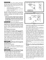
background image

5

EXTENSION CORDS


Use  proper  extension  cords.  Make  sure 

your  extension  cord  is  in  good  condition  and  is  a  3-wire 

extension cord which has a 3-prong grounding type plug 

and matching receptacle which will accept the machine’s 

plug.  When  using  an  extension  cord,  be  sure  to  use  one 

heavy  enough  to  carry  the  current  of  the  machine.  An 

undersized cord will cause a drop in line voltage, resulting 

in  loss  of  power  and  overheating.  Fig.  D-1  shows  the 

correct  gauge  to  use  depending  on  the  cord  length.  If  in 

doubt, use the next heavier gauge. The smaller the gauge 

number, the heavier the cord.

Fig. D-1

MINIMUM gAUgE EXTENSION CORD 

RECOMMENDED SIZES FOR USE WITH STATIONARY ELECTRIC MACHINES

  Ampere 


Total Length 

gauge of 


Rating 

Volts 

of Cord in Feet 

Extension Cord


0-6 

120 

up to 25 

18 AWg 

  0-6 

120 

25-50 

16 AWg 

  0-6 

120 

50-100 

16 AWg 

  0-6 

120 

100-150 

14 AWg

  6-10 

120 

up to 25 

18 AWg 

  6-10 

120 

25-50 

16 AWg 

  6-10 

120 

50-100 

14 AWg 

  6-10 

120 

100-150 

12 AWg      

  10-12 

120 

up to 25 

16 AWg 

  10-12 

120 

25-50 

16 AWg 

  10-12 

120 

50-100 

14 AWg 

  10-12 

120 

100-150 

12 AWg

  12-16 

120 

up to 25 

14 AWg 

  12-16 

120 

25-50 

12 AWg 

  12-16 

120 

gREATER THAN 50 FEET NOT RECOMMENDED

FOREWORD
The PORTER-CABLE PC400AP will connect to woodworking machines that accept a 4" diameter hose. This model PC400AP comes 

with one 5 micron upper bag, one lower plastic bag and a 4" x 5 ft. collection hose.
NOTE: 

The picture on the manual cover illustrates the current production model. All other illustrations contained in the manual are 

representative only and may not depict the actual labeling or accessories included. These are intended to illustrate technique only.

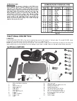
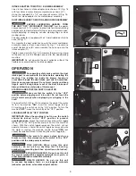
FUNCTIONAL DESCRIPTION

CARTON CONTENTS

1. 

Motor and blower assembly

2. 

Base

3. 

Wheel casters (4)

4. 

Side support

 (2)

5. 

Upper bag 

6. 

Lower bag

7. 

Filter bag clamp (2)

8. 

Support

9. 

Support rod base

10. 

Support rod

11. 

Hose

12. 

Hose clamp (2)

13. 

5/16-18 x 5/8" Hex head screw (12)

14. 

5/16 Lockwasher (12)

15. 

5/16-18 Hex nut (9)

16.  

3/8 Lockwashers (4) for casters

17.  

3/8-16 Hex nuts (4) for casters

18. 

#8 x 1/2" Countersunk Screws (4) 


for attaching dust hose inlet port

19. 

Intake adapter

20. 

Switch toggle

1

2

3

4

5

6

7

8

9

10

11

12

13

14

15

16

17

18

19

20

Summary of Contents for N066288

Page 1: ...tercable com INSTRUCTIVO DE OPERACI N CENTROS DE SERVICIO Y P LIZA DE GARANT A ADVERTENCIA L ASE ESTE INSTRUCTIVO ANTES DE USAR EL PRODUCTO CATALOG NUMBER PC400AP Colector de polvo monoet pico de un H...

Page 2: ...g matches cigarettes or hot ashes EXPLOSION HAZARD Do not use this unit to vacuum combustible explosive materials coal grain or other finely divided combustible material HEALTH HAZARD Do not use this...

Page 3: ...rk area before leaving the area Do not place open end of dust collection hose anywhere near the eyes or ears while operating Keep your work area clean and well lit Cluttered benches and dark areas inv...

Page 4: ...t the operator from electric shock 1 All grounded cord connected machines In the event of a malfunction or breakdown grounding provides a path of least resistance for electric current to reduce the ri...

Page 5: ...G 10 12 120 25 50 16 AWG 10 12 120 50 100 14 AWG 10 12 120 100 150 12 AWG 12 16 120 up to 25 14 AWG 12 16 120 25 50 12 AWG 12 16 120 greater than 50 feet not recommended FOREWORD The PORTER CABLE PC40...

Page 6: ...MATE Assembly for this machine takes approximately 1 2 hours CASTERS 1 Locate the bag of hardware with the four 3 8 hex nuts and four 3 8 lockwashers for the four casters 2 For each wheel insert bolt...

Page 7: ...shows the motor and blower assembly attached to the side supports SUPPORT 1 Place the support A Fig 9 inside the two side supports NOTE MAKE SURE SUPPORT A IS ATTACHED TO THE SIDE SUPPORTS CLOSEST TO...

Page 8: ...support rod at this time If adjustment is necessary loosen nut A Fig 11 and rotate support rod B Fig 11 as needed to obtain proper rod height to support filter bag F Tighten nut A Fig 11 6 Place lock...

Page 9: ...s and all foreign objects out of the dust intake port Always follow the safety rules of this manual STARTING AND STOPPING DUST COLLECTOR Make sure that the switch is in the OFF position before pluggin...

Page 10: ...of the information shown on the nameplate of your tool model number type serial number etc Accessories Since accessories other than those offered by Porter Cable have not been tested with this produc...

Page 11: ...combustible RISQUES POUR LA SANT Ne pas aspirer des mati res dangereuses toxiques ou canc rig nes comme l amiante un pesticide ou des r sidus de peinture au plomb Ne laissez jamais seul un d poussi re...

Page 12: ...Ranger le cordon d alimentation de fa on s curitaire pour emp cher le risque de tr buchement Grave danger de lac ration Arr ter l appareil et le d brancher du secteur puis attendre 2 1 2 minutes l ar...

Page 13: ...errupteur se trouve la position OFF ARR T INSTRUCTIONS DE MISE LA TERRE RISQUES DE CHOCS LECTRIQUES Cette machine doit tre mise la terre pendant son emploi afin de prot gerl utilisateur des d charges...

Page 14: ...4 po de diam tre Le mod le PC400AP est livr avec un sac sup rieur de 5 microns un sachet en plastique inf rieur et un tuyau collecteur de 10 cm x 1 5 m 4 po x 5 pi REMARQUE La illustration de la couv...

Page 15: ...llerie qui contient les quatre crous hexagonaux de 3 8 po 9 5 mm et les quatre rondelles de blocage pour les quatre roulettes 2 Pour chaque roulette ins rer le boulon de la roulette dans les trous A f...

Page 16: ...aux PLAQUE DE SUPPORT 1 Ins rer la plaque de support A fig 9 l int rieur des deux supports lat raux B REMARQUE S ASSURER QUE LA PLAQUE DE SUPPORT EST BIEN FIX E DU C T DES SUPPORTS LAT RAUX LE PLUS PR...

Page 17: ...re de r gler la hauteur de la tige de support du tambour cette tape Le cas ch ant desserrer l crou A fig 11 et tourner la tige de support B fig 11 au besoin pour obtenir la hauteur correcte pour soute...

Page 18: ...d sarm ou un fusible grill toujours d placer l interrupteur en position d arr t OFF jusqu ce que l alimentation soit r tablie RISQUES D INCENDIE Lors de l utilisation du d poussi reur ne pas aspirer...

Page 19: ...ur de plus amples renseignements par courrier crire PORTER CABLE 4825 Highway 45 North Jackson Tennessee 38305 888 848 5175 U l attention de Product Service S assurer d indiquer toutes les information...

Page 20: ...20 REMPLACEMENT DES TIQUETTES D AVERTISSEMENT Si vos tiquettes d avertissement sont illisibles ou manquantes contactez le 888 848 5175 pour en obtenir le remplacement gratuit...

Page 21: ...polvo sin supervisi n cuando est enchufada Desench fela cuando no est en uso y antes de repararla Para reducir el riesgo de una descarga el ctrica no utilice en el exterior o sobre superficies h meda...

Page 22: ...de laceraci n grave Ponga la unidad en off desenchufe la unidad de la fuente de alimentaci n el ctrica y espere 2 1 2 minutos para permitir que las piezas de rotaci n internas se detengan completamen...

Page 23: ...st cableada para corriente alterna de 120 V 60 Hz Antes de conectar la m quina a la fuente de alimentaci n aseg rese de que el interruptor est en la posici n de apagado OFF INSTRUCCIONES DE CONEXI N A...

Page 24: ...que sea lo suficientemente pesado como para llevar la corriente de la m quina Un cord n de tama o insuficiente causar una ca da de la tensi n de la l nea el ctrica que dar como resultado p rdida de p...

Page 25: ...a bolsa de herrajes que contiene las cuatro tuercas hexagonales de 3 8 y las cuatro arandelas de seguridad de 3 8 para las cuatro ruedecillas 2 Para cada ruedecilla introduzca el perno de la ruedecill...

Page 26: ...base MONTAJE DEL TABLERO FIRME 1 Coloque el tablero firme A Fig 9 en el interior de los dos tableros laterales NOTA ASEG RESE DE QUE EL TABLERO FIRME A EST SUJETO A LOS TABLEROS LATERALES M S CERCANOS...

Page 27: ...orte del tambor en este momento Si es necesario realizar un ajuste afloje la tuerca de fijaci n A Fig 11 y gire la varilla de soporte B Fig 11 seg n sea necesario para obtener la altura apropiada de l...

Page 28: ...icio de entrada de polvo El ventilador que gira ubicado en el interior de la carcasa del soplador es accesible a trav s del orificio de entrada de polvo y puede ser peligroso Use siempre indumentaria...

Page 29: ...obra No podemos otorgar garant as en relaci n con las reparaciones ni los intentos de reparaci n de otras personas Si llama a este n mero tambi n encontrar las respuestas a las preguntas m s frecuent...

Page 30: ...taci n razonablemente erogados derivados del cumplimiento de este certificado Para hacer efectiva esta garant a deber presentar su herramienta y esta p liza sellada por el establecimiento comercial do...

Page 31: ...1525 Col San Luis 444 814 2383 TORREON COAH Blvd Independencia 96 Pte Col Centro 871 716 5265 VERACRUZ VER Prolongaci n D az Mir n 4280 Col Remes 229 921 7016 VILLAHERMOSA TAB Constituci n 516 A Col...

Page 32: ...WORK LIFE MAX FORCE MAX LIFE Micro Set Midi Lathe Monsoon MONSTER CARBIDE Network OLDHAM Omnijig PC EDGE Performance Crew Performance Gear Pocket Cutter Porta Band Porta Plane Porter Cable PORTER CAB...

Reviews: