


Page 5
PUSH PRO -0120843
SPECIAL LIMITATIONS
Elevating the platform is limited to firm, level surfaces
only.
DANGER:
THE ELEVATING FUNCTION SHALL ONLY BE
USED WHEN THE WORK PLATFORM IS LEVEL AND ON
A FIRM SURFACE.
The work platform is NOT intended to be pushed over
uneven, rough, or soft terrain.
PLATFORM CAPACITY
One person and tools may occupy the platform when
the machine is indoors only. The maximum platform
capacity for the aerial platform is stated in the
“Specifications” on pages 16 to 18.
DANGER:
DO NOT EXCEED THE MAXIMUM PLATFORM
CAPACITY OR THE PLATFORM OCCUPANCY LIMITS FOR
THIS MACHINE.
MANUAL FORCE
Manual force is the force applied by the occupants to
objects such as walls or other structures outside the
work platform. In zero wind conditions the maximum
allowable manual force is limited to 200 N.
DANGER:
DO NOT EXCEED THE MAXIMUM AMOUNT OF
MANUAL FORCE FOR THIS MACHINE.
LIFT LEVEL SENSOR INTERLOCK
The aerial platform lift function is interlocked through a
level sensor system.
If the chassis is tilted more than 2 degrees side-to-side
or front-to-rear, an alarm will sound when the power is
turned on and the lift function will not operate. When
LOWERING ALARM
When a platform control button is pressed to lower
the platform, the alarm emits a loud beeping sound to
warn personnel in the work area to stand clear.
DANGER:
PINCH POINTS EXIST ON THE SCISSORS
STRUCTURE. DEATH OR SERIOUS INJURY WILL
RESULT IF THE SCISSORS STRUCTURE LOWERS ONTO
PERSONNEL WITHIN THE SCISSORS ARMS OR UNDER
THE RAISED PLATFORM. STAND CLEAR WHILE RAISING
AND LOWERING THE PLATFORM.
Be careful when lowering the platform. Keep hands
and fingers away from the scissors structures
components.
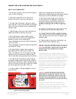
LOWERING INTERRUPT
When the platform is lowered to about 1.5 m (5′)
lowering stops. The platform will not lower for ve
seconds regardless of the control position to allow
personnel to clear the area of the scissors before the
platform completely lowers.
Release the control to reset the lowering function, then
continue to lower the platform.
the alarm sounds, only the platform lower function will
operate.
Position the machine on a level surface when the
lift level sensor alarm sounds. When the machine is
properly positioned on a level surface, the alarm will
not sound and all functions will be operational.
The lift level sensor system is for added protection and
does not justify operating on anything other than firm,
flat, level surfaces.
3
4
5
6
7
3,4~5,4
5,4~8,0
8,0~10,8
10,8~139
13,9~17,2
12,25~19,4
19,4~28,8
28,8~38,9
38,9~50,0
50,0~61,9
11,5~17,75
17,75~26,25
26,25~35,5
35,5~45,5
45,5~56,5
7,5~12,0
12,0~18
18~24,25
24,5~31
31~38,5
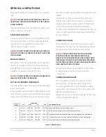
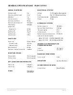
Papers and thin branches move, flags wave.
Dust is raised, papers whirl up, and small branches sway.
Shrubs with leaves start swaying. Wave crests are apparent in ponds/swamps.
Tree branches move. Power lines whistle. It is difficult to open an umbrella.
Whole trees sway. It is difficult to walk against the wind.
Beaufort
Rating
WIND SPEED
m/s
km/h
ft/s
mph
GROUND CONDITIONS
Figure 1 - Beaufort Scale


