POP UP PUSH 10 PRO Operator'S Safety And Maintenance Handbook Download Page 4

Page 3

PUSH PRO -0120843

SAFETY RULES

WARNING:

 ALL PERSONNEL SHALL CAREFULLY READ, UNDERSTAND AND FOLLOW ALL SAFETY RULES 

AND OPERATING INSTRUCTIONS BEFORE OPERATING OR PERFORMING MAINTENANCE ON ANY POP UP 
AERIAL WORK PLATFORM.

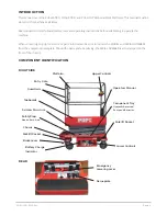
USE OF THE AERIAL WORK PLATFORM: 

This aerial work platform is intended to lift persons and his tools as well as the material 

used for the job. It is designed for repair and assembly jobs and assignments at overhead workplaces (ceilings, buildings etc.). Uses or 

alterations to the aerial work platform must be approved by Pop Up.

THIS AERIAL WORK PLATFORM IS NOT INSULATED! 

For this reason it is imperative to keep a safe distance from live parts of 

electrical equipment!
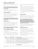
Exceeding the specifed permissible maximum load is prohibited! See “Platform Capacity” on page 5 for details. The use and operation 

of the aerial work platform as a lifting tool or a crane is prohibited!

NEVER 

exceed the manual force allowed for this machine. See “Manual Force” on page 5 for details.

 DISTRIBUTE

 all platform loads evenly on the platform.

NEVER 

operate the machine without first surveying the work area for surface hazards such as holes, drop-offs, bumps, curbs, or 

debris; and avoiding them.

OPERATE 

machine only on surfaces capable of supporting wheel loads.

NEVER

 operate the machine outdoors or indoors when wind speeds exceed 0 m/s (0 mph).

Do not operate the aerial platform in windy or gusty conditions. Do not add anything to or take anything into the aerial platform that 

will increase the wind loading such as billboards, banners,  ags, etc.

IN CASE OF EMERGENCY 

push EMERGENCY STOP switch to deactivate all powered functions.

IF ALARM SOUNDS 

while platform is elevated, STOP, carefully lower platform. Move machine to a  rm, level surface.

Climbing up the railing of the platform, standing on or stepping from the platform onto buildings, steel or prefab concrete structures, 

etc., is prohibited!
Dismantling the entry gate or other railing components is prohibited! Always make certain that the entry gate is closed! It is prohibited 

to keep the entry gate in an open position when the platform is raised!
To extend the height or the range by placing of ladders, scaffolds or similar devices on the platform is prohibited!

NEVER 

perform service on machine while platform is elevated without blocking elevating assembly.
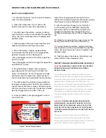
INSPECT 

the machine thoroughly for cracked welds, loose or missing hardware, hydraulic leaks, loose wire connections, and 

damaged cables or hoses before using.

VERIFY 

that all labels are in place and legible before using

.

NEVER 

use a machine that is damaged, not functioning properly, or has damaged or missing labels.

To bypass any safety equipment is prohibited and presents a danger for the persons on the aerial work platform and in its working 

range.

NEVER 

charge batteries near sparks or open flame. Charging batteries emit explosive hydrogen gas. Modifications to the aerial work 

platform are prohibited or permissible only at the approval by Pop Up.

AFTER USE

secure the work platform from unauthorized use by turning the keyswitch off and removing key. The driving of MEWP’s 

on the public highway is subject to national traf c regulations.
Certain inherent risks remain in the operation of this machine despite utilizing proper design practices and safeguarding. Care must 

be taken to ensure that the machines meets the requirements of stability during use, transportation, assembly, dismantling when out 

of service, testing, or foreseeable breakdowns.
In the event of an accident or breakdown see “Emergency Lowering” on page 11, do not operate the aerial platform if it is damaged 

or not functioning properly. Quali ed maintenance personnel must correct the problem before putting the aerial platform back into 

service.

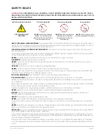
ELECTROCUTION HAZARD

TIP OVER HAZARD

COLLISION HAZARD

FALL HAZARD

THIS MACHINE IS NOT 

INSULATED!

NEVER

 elevate the platform 

or drive the machine while 

elevated unless the machine is 

on a firm, level surface.

NEVER

 position the platform 

without first checking for 

overhead obstructions or 

other hazards.

NEVER

 climb, stand, or sit on 

platform guardrails or midrail.

Summary of Contents for PUSH 10 PRO

Page 1: ...PUSH PRO OPERATOR S SAFETY AND MAINTENANCE HANDBOOK FOR PUSH 6 PRO PUSH 8 PRO PUSH 10 PRO 44 0 1244 833 933 info popupproducts co uk popupproducts co uk FOR PUSH 6 PRO PUSH 8 PRO AND PUSH 10 PRO ...

Page 2: ...ON LOWER CONTROLS UPPER CONTROLS PUSH PRO 0120843 2 3 4 4 5 5 5 5 5 5 6 6 6 6 7 7 7 7 7 7 7 8 9 10 10 10 10 OPERATOR S SAFETY AND MAINTENANCE HANDBOOK FOR PUSH 6 PRO PUSH 8 PRO PUSH 10 PRO PLATFORM Raising and Lowering Lowering Interrupt COMPONENT TRAY EMERGENCY LOWERING TRANSPORTING THE MACHINE Preparing for Transportation Transporting Lifting with a Forklift Lifting with a Tail Lift MAINTENANCE ...

Page 3: ...Amendment A2 2009 Council Directive 2004 108 EC on Electromagnetic Compatibility Council Directive 2006 95 EC on Low Voltage Equipment Safety TYPE APPROVAL IN ACCORDANCE WITH 2006 42 EC PERFORMED BY Powered Access Certification LTD P O Box 98 Windermere Cumbria LA23 1WF UK Notified Body Identification Number 0545 E C TYPE EXAMINATION CERTIFICATE NO AUTHORIZED REPRESENTATIVE IN EUROPEAN UNION The T...

Page 4: ...s is prohibited Always make certain that the entry gate is closed It is prohibited to keep the entry gate in an open position when the platform is raised To extend the height or the range by placing of ladders scaffolds or similar devices on the platform is prohibited NEVER perform service on machine while platform is elevated without blocking elevating assembly INSPECT the machine thoroughly for ...

Page 5: ...rts information be sure to include the MODEL and SERIAL NUMBERS from the equipment nameplate Should the nameplate be missing the SERIAL NUMBER is also stamped on the front of the chassis COMPONENT IDENTIFICATION RIGHT SIDE REAR Platform Upper Controls Operators Manual Component Tray Hydraulic Reservoir Pump and Batteries Forklift Pocket Lower Controls Entry Gate Guardrails Toeboards Scissors Struc...

Page 6: ...WILL RESULT IF THE SCISSORS STRUCTURE LOWERS ONTO PERSONNEL WITHIN THE SCISSORS ARMS OR UNDER THE RAISED PLATFORM STAND CLEAR WHILE RAISING AND LOWERING THE PLATFORM Be careful when lowering the platform Keep hands and fingers away from the scissors structures components LOWERING INTERRUPT When the platform is lowered to about 1 5 m 5 lowering stops The platform will not lower for ve seconds regar...

Page 7: ...n the chassis and on the upper control panel in the platform LOWER CONTROLS The lower controls refer to Figure 2 are located on the right side of the chassis The following are located on the lower control panel Emergency stop button Control selector switch Ground operation button Platform raise lower buttons Battery charger selector plugs indicator WARNING THE AERIAL PLATFORM IS FREE TO MOVE WHEN ...

Page 8: ...following controls are located on the upper control panel Interlock button Battery condition indicator Platform raise lower buttons Emergency stop button WARNING THE AERIAL PLATFORM IS FREE TO MOVE WHEN THE BRAKES ARE RELEASED DEATH OR SERIOUS INJURY CAN RESULT ENGAGE THE BRAKES BEFORE OPERATING THE AERIAL PLATFORM EMERGENCY STOP BUTTON The emergency stop is a two position red push button on the r...

Page 9: ... pages 16 to 18 3 Check weekly that the uid level in the batteries is correct See Battery Maintenance on page 15 4 Verify that the batteries are charged daily 5 Check daily that the AC extension cord has been disconnected from the outlet on the side of the chassis 6 Inspect the brakes daily on the rear castor wheels for proper operation Step down on the brake levers and verify that the machine wil...

Page 10: ...nd hold the ground operation button inward Test each machine function from the lower control station refer to Figure 2 6 Test the emergency lowering system for proper operation 7 Push the Lower Control Emergency Stop Button to check for proper operation All machine functions should be disabled Pull the Lower Control Emergency Stop Button outward to resume 8 Enter the platform and close the gate 9 ...

Page 11: ...SULT FROM A TIP OVER ACCIDENT DO NOT EXCEED THE CAPACITY VALUES INDICATED ON THE PLATFORM RATING PLACARD Capacity values indicate the rated lifting capacity and do not indicate aerial platform stability The operator bears ultimate responsibility for ensuring that the aerial platform is properly set up for the particular conditions encountered PREPARING FOR OPERATION Use the following procedure to ...

Page 12: ...interlock button on the left side of the upper control box To raise the platform press and hold the platform raise button until the desired height is reached To lower the platform press and hold the platform lower button until the desired height is reached LOWERING INTERRUPT When the platform is lowered to about 1 5m 5 lowering stops The platform will not lower for five seconds regardless of the j...

Page 13: ... following procedure to lift the aerial platform with a forklift 1 Properly stow the aerial platform 2 Engage the brakes on both of the rear wheels 3 Remove all personnel tools materials or other loose objects from the platform 4 Insert the forklift forks into the pockets on either side of the machine CAUTION LIFTING THE AERIAL PLATFORM WITH THE FORKLIFT FORKS POSITIONED IMPROPERLY CAN PRODUCE ENO...

Page 14: ... ALWAYS WEAR SAFETY GLASSES WHEN WORKING NEAR THE BATTERY BATTERY FLUID IS HIGHLY CORROSIVE THOROUGHLY RINSE AWAY ANY SPILLED FLUID WITH CLEAN WATER ALWAYS REPLACE THE BATTERY WITH A MANUFACTURER APPROVED REPLACEMENT Check the battery fluid level weekly especially if the machine is being used in a warm dry climate If electrolyte level is lower than 6 mm 1 4 above the plates add distilled water onl...

Page 15: ...itself off it is not necessary to immediately unplug the extension cord from the battery charger The charger will monitor the charge state of the battery and recharge them if the voltage drops off 10 Slide the component tray open to access the battery Remove the caps from the battery 11 Visually check the battery uid level making sure the level is within 6 mm 1 4 of the bottom of the ller neck ins...

Page 16: ...der all pages readable and intact Clean connectors tight Proper operation Proper operation No wear or physical damage Between full and add marks with platform stowed No leaks all fittings tight Good condition no damage smooth movement Proper operation no damage or deformation Proper operation Shuts off lower controls proper operation Sounds when platform lowers proper operation Proper operation No...

Page 17: ...s 6 to 10 seconds Side to side Front to rear LIFT LEVEL SENSOR INTERLOCK 2 degrees 2 degrees TIRES Nonmarking solid rubber Voltage Source Fluid Recommended Charger ELECTRICAL SYSTEM 12 V DC negative chassis ground One 12 V 105 amp hour battery distilled water 15 amp Maximum pressure Pressure Relief Valve Setting Reservoir capacity System capacity Maximum operating temperature Hydraulic fluid recom...

Page 18: ...s 8 to 12 seconds Side to side Front to rear LIFT LEVEL SENSOR INTERLOCK 2 degrees 2 degrees TIRES Nonmarking solid rubber Voltage Source Fluid Recommended Charger ELECTRICAL SYSTEM 12 V DC negative chassis ground One 12 V 105 amp hour battery distilled water 15 amp Maximum pressure Pressure Relief Valve Setting Reservoir capacity System capacity Maximum operating temperature Hydraulic fluid recom...

Page 19: ...10 to 14 seconds Side to side Front to rear LIFT LEVEL SENSOR INTERLOCK 2 degrees 2 degrees TIRES Nonmarking solid rubber Voltage Source Fluid Recommended Charger ELECTRICAL SYSTEM 12 V DC negative chassis ground One 12 V 105 amp hour battery distilled water 15 amp Maximum pressure Pressure Relief Valve Setting Reservoir capacity System capacity Maximum operating temperature Hydraulic fluid recomm...

Page 20: ...Pop Up Products Limited Vigo Centre Birtley Road Washington Tyne Wear NE38 9DA UK Call 44 0 845 1550 057 Fax 44 0 845 1557 756 ...

Reviews: