background image


  6.   Mounting 

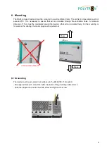
The QAM compact headend must be mounted in a well ventilated room. The ambient temperature must not 
exceed  45°C.  It  is  necessary  to  ensure  that  air  can  circulate  through  the  ventilation  holes.  A  minimum 
distance of 15 cm must be maintained around the device so that air can circulate freely. For the mounting or 
for work on the cabling, the mains plug must be pulled out.  


= Heat accumulation!!!


  6.1  Grounding 

The device must be grounded in accordance to the EN 60728-11 standard. 

    - Strip approximately 15 mm of the cable insulation of the grounding cable (4mm

2

). 

- Slide the stripped end under the earth screw and tighten the screw.  


15cm 

15cm 

Summary of Contents for QAM 12 LAN

Page 1: ...QAM 12 LAN Compact Headend with LAN port Manual MADE IN GERMANY 0902266 V1...

Page 2: ...ice parameters____________________________ 11 8 2 1 Input parameters____________________________________________ 12 8 2 2 Output parameters __________________________________________ 13 8 2 3 Edit ser...

Page 3: ...y dripping and splashing water If there is condensation wait until the device is completely dry Operating environment according to the specified IP protection class Caution Danger of risk to life Acco...

Page 4: ...efined packing and transportation materials Damage caused by faulty connections and or improper handling are excluded from any liability Waste disposal Electronic equipment does not belong in househol...

Page 5: ...TV with integrated DVB C tuner It is not relevant whether the individual programs are broadcast in HDTV pay TV or free to air signals The programming is done via laptop PC by means of programming soft...

Page 6: ...nce of 15 cm must be maintained around the device so that air can circulate freely For the mounting or for work on the cabling the mains plug must be pulled out Heat accumulation 6 1 Grounding The dev...

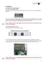
Page 7: ...LNB power supply is indicated by an LED Please note the current consumption of each input may not exceed 250 mA A total of 500 mA is available SAT signal feed directly to the tuner Remove the screws...

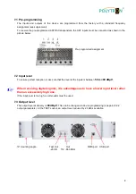
Page 8: ...reception make sure that the level at the inputs is between 50 and 80 dB V When receiving digital signals it is advantageous to have a lower input level rather than an excessively high one If the inp...

Page 9: ...nload the software package from the homepage www polytron de SATC12_Vxxx zip and unzip in the directory of your choice e g C QAM12 The software can also be loaded from the enclosed USB stick 8 1 1Inst...

Page 10: ...d After the installation of the programming software on the PC the QAM 12 LAN can be connected to the PC with the USB cable If USB access from the outside of the unit is not desired the USB connection...

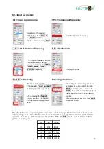
Page 11: ...rs of all 12 channels will be displayed For a better overview the menu is split into channels 1 6 and 7 12 across two pages Via this menu all settings of the input and output parameters can be done Th...

Page 12: ...rror rate is displayed in the upper field BER and the signal to noise ratio SNR These depend on the quality of the reception conditions and the SAT After pressing the Search signals button the data is...

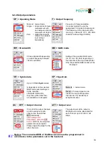
Page 13: ...QAM modes will be displayed SR Symbol rate SP Spectrum Up to 7 200 kiloSymbole sec Is dependent on the selected Normal normal mode QAM mode used settings in Cable networks Invers Primary signal can be...

Page 14: ...on the input will be displayed On the right side the services in the output signal will be displayed After scan for services all services from the input are also available at the output If the data ra...

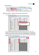
Page 15: ...sorted in the table in numerical order Programs which have no LCN assigned are placed below those programs that are assigned LCNs The column Remap SID allows the reassignment of an SID Please ensure t...

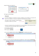
Page 16: ...ned A directory and a file name e g Anlage should be entered for this The file name must retain the ending c12 Additionally a rtf file will be saved in the same folder The rtf file can be opened edite...

Page 17: ...vice The basic configurations will be loaded and the adjustment interface will be started The standard IP address of QAM 12 LAN is 192 168 001 227 If the system is used in a network with a different n...

Page 18: ...of saving is displayed on the status diagram This process can last for up to a minute Now close the program and remove the USB cable Then connect the QAM 12 LAN to the network All PCs in the network c...

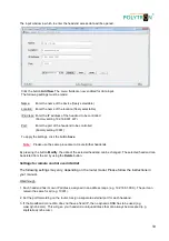
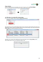
Page 19: ...g the button Modify the data of the selected headend can be changed The selected headend can be deleted from the list by using the Delete button Settings for remote control over internet The following...

Page 20: ...the headend can be done via a double click in the first column in the space directly to the left of the headend to be opened After that the Program Menu of the selected headend will be opened Afterwa...

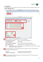
Page 21: ...rs Maximum Operating Temperature maximum measured environmental temperature Critical Operating Hours operating hours at environmental temperature over 45 C Note The temperatures shown only correspond...

Page 22: ...uner locked green flashing Tuner not locked FPGA green configured ready to operate off error ASI green interfaces OK off error RF green output OK off error Status green all tuners locked ready for use...

Page 23: ...turn off the unit or unplug the power cord from the wall outlet Failure to follow the instructions or interrupt the power supply while installing the new controller software may interrupt the update p...

Page 24: ...up to date the following menu window will be displayed 8 7 Function Password The menu item Password Settings allows changes of the access data to the device and for increased access security It is fou...

Page 25: ...type the password in the input field Retype Password Click on Save to store the password settings By clicking on Change Password a new password will be created You can also deactivate the password pro...

Page 26: ...l tuner inputs are connected via the SAT input matrix Factory setting Example 2 The tuner inputs are connected via the SAT input matrix and 2 additional inputs from another satellite are connected via...

Page 27: ...3 5 2 3 3 4 5 6 8 9 9 10 Roll off 0 35 0 25 0 20 Output modulation DVB C Modulation 16QAM 32QAM 64QAM 128QAM 256QAM FEC Reed Solomon 204 188 Symbol rate 1 7 2 MS s Bandwidth 7 8 MHz dependent of SR 0...

Page 28: ...hme H Q Order department 49 0 70 81 1702 0 Technische Hotline Technical hotline 49 0 70 81 1702 0 Telefax 49 0 70 81 1702 50 Internet http www polytron de Email info polytron de Technische nderungen v...

Reviews: