46
47
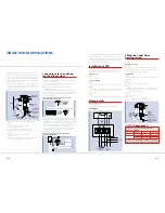
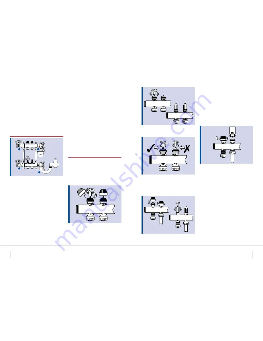
Slowly open the valve by turning the spindle anti-clockwise
until the required flow rate in l/min is achieved in the flow
meter window.
When adjusting the manifold flow rates care should be taken
to ensure that the adjustment spindle is not left with any of the
thread showing.
In order to carry out any maintenance to the installation it is
possible to isolate individual circuits by closing both the flow
and return ports, as shown in the diagram below.
NOTE:
The isolating valve fitted to the manifold flow meter
is not used for balancing purposes.
If it becomes necessary to close off a manifold completely,
this can be done by using a ¾” brass cap with a suitable rubber
washer insert.
Once all of the circuit flow rates have been adjusted the
system should be left to operate for a short period whilst any
remaining air is removed. Once this has been done the flow
rates should be re-checked and adjusted if necessary before the
actuator heads are fitted. If the actuator heads are not likely
to be fitted for a while then it is recommended that the blue
caps are used in order to protect the flow rate settings and
prevent any debris from entering the flow valve assembly.
IMPORTANT NOTE:
When using the PB970014 Modulating
Pump Unit to ensure that the primary boiler flow temperature
provided at the manifold is at least 15°C hotter than the
required manifold operating temperature. This is due to
the fact that this manifold uses an ‘injector method’ to mix
down the primary water. Furthermore, when balancing the
system with this particular manifold kit please ensure that the
modulating pump is set to a fixed head speed whilst making
any adjustments.
SYSTEM COMMISSIONING
Initial system filling
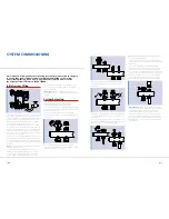
Close the manifold isolating valves (1) & (2). Connect a hose pipe
to the manifold return drain off point (4) and take to a drain.
Connect a second hose to the manifold filling point (3) and attach
to a mains cold water supply (3 bar max). The connections to
the manifold drain and fill points are ¾” BSP. Use flexible ¾”
tap connectors for the simplest method of connection.
Close all under floor heating circuits except one, by screwing
down the blue caps and closing the isolating valves situated on
top of the manifold flow meter. Flush the first circuit with mains
cold water until all of the air has been purged. Once this has
been done close the first circuit and repeat the process for all of
the other circuits on the manifold.
Once the system has been filled and purged of air, and before
any screed is laid, a system pressure test must be carried out to
confirm the integrity of the installation. It is recommended that
this test be done using a suitable hydraulic pressure test kit and
not with air.
NOTE:
The system pressure test should be carried out with the
manifold pump pack removed.
Close the manifold isolating valves and connect the pressure
test pump to the manifold flow rail using the ¾” threaded
connection on the filling/drain-off point (3). Pressurise the
system to 6 bar max and leave under pressure for 1 hour.
Once the pressure test is complete reduce the system pressure
down to 3 bar to protect the pipework whilst any screeding
process is carried out.
IMPORTANT NOTE:
Do not leave the system under pressure
during periods of extreme cold weather or when there is a risk
of freezing.
System balancing
Once the system is up and running it is necessary to balance the
system in accordance with the design data provided.
This should be done using the following method:
Ensure that the boiler and main system duty pump are operating
correctly and that sufficient heat input and flow rates are being
provided at the manifold(s).
Set the under floor heating controls to call for heat and
check to see that the two-port zone valve and manifold pump
are energised.
Remove the blue cap from the manifold flow port and,
using the bleed key provided, turn the flow adjustment spindle
clockwise to completely close the circuit.
Once installed, Polypipe under floor heating systems should be tested thoroughly
to ensure they are working effectively, including initial filling of the system
and system balancing. If you require any further information please contact
the Polypipe Technical Team on 01709 770000.
1
2
4
3

