Polypipe Under Floor Heating Systems Technical Installation Manual Download Page 23

44

45

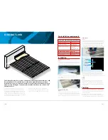
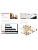
SINGLE ROOM APPLICATIONS

All Polypipe under floor heating systems can be installed 
in single rooms and connected to the existing wet heating 
system. In rooms greater than 30m

2

 it is recommended that 

the connection to the under floor heating system is made via 
a manifold and installed in the same way as a multiple room 
installation with single area control.
Areas of up to 30m

2

 should use the Polypipe Zonal Regulation 

unit (ZRU) as this provides a simpler method of connecting 
into the existing system, without the need for expensive 
hydraulic or electrical alterations.


The ZRU simply connects to the existing heating system 
providing: 
•  Water temperature control (30°C to 60°C) 
  for the under floor heating  
•  The correct flow rate the under floor heating 
•  Automatically switches On and Off via a built-in 
  pipe thermostat  
•  A wiring connection for a room thermostat 
  or wireless sensor  
•  Can be connected to operate the under floor heated 
  room independently with the existing system 

Connections to the existing 

wet heating system 

The pipe work connections to the ZRU are for 15mm diameter 
pipe and the ZRU should not be connected to the system from 
any pipe smaller than 15mm.
A small number of boilers can be affected hydraulically by the 
use of a second pump in the system.

NOTE: 

Check with the boiler manufacturer to ensure 

compatibility with the ZRU.
The preferred connection to the ZRU is to the main flow and 
return pipe work of a 2 pipe system, i.e typically from 22mm 
distribution pipe work. However it can also be connected to the 
nearest existing radiator.

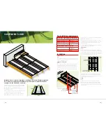
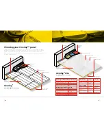
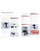
Pipe connection to operate under floor heating 
at the same time as the boiler 


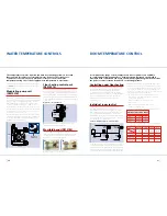
The diagram above shows the ZRU connected to operate with the 
boiler on/off firing. Due to the quick response of low mass systems 
(Overlay™, Overlay™ Lite, MHP, etc) this is likely to be suitable. 
Using this method for solid floor installations may require the 
timings of the existing heating to be altered to allow the under 
floor heating system to reach comfort temperature.
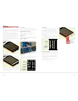
If the room is to be controlled independently of the existing 
central heating system, a zone valve needs to be installed 
between the boiler and the ZRU.

Pipe connection to operate ZRU / under floor 
heating independently

Programmable room thermostat

Connection 

from main 

distribution

pipe work

Zone

valve to

under

floor

heating

Zone valve 

to radiator, etc

Connection 

from main 

distribution 

pipe work

Connection 

from nearest 

radiator

260mm

200mm

Pump

Pipe

thermostat

Heating 

return

Heating 

flow

Under floor 

heating flow

Under floor 

heating return

Thermostatic 

blending valve

Pump speed 

control

Tees and spigot 

elbows for 

second circuit 

if required

Room stat (example) - not supplied

Pump

Remove 

link if 

using a

room 

thermostat

Boiler feed thermostat

42°C close

31°C open

Mains

(Fused spur)

3amp

The pipe supplying the ZRU should be connected to the main boiler 
distribution pipe prior to the connection of other zone valves.
A programmable room thermostat can be used to operate the 
zone valve and, in turn, the end switch within the zone valve 
can provide a signal to fire the boiler. 
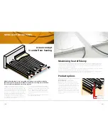
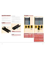
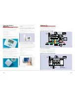
Installation of ZRU  

The ZRU can be positioned either in the room where the under 
floor heating is installed or in an adjacent area, 300mm from 
the finished floor level to allow for pipe connections.
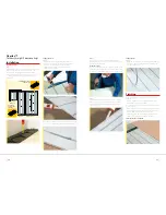
Fitting the ZRU


Step 1:

Screw unit to wall.

Connecting the ZRU 

Step 2:

Connect heating pipe work via an isolation valve (as shown).

Step 3:

Connect under floor heating circuit(s) using an isolation valve. 
Use tees and spigot elbows to form connections for 2 and 3 
circuit systems.

Step 4:

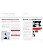
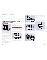
Connect mains wiring (as diagram below) via a fused spur. 

Wiring details  

IMPORTANT NOTE:

 If in any doubt you should contact 

a qualified electrician.
The water temperature must be 45°C to operate the unit.

Wiring diagram

Filling the under floor 

heating system   

Use the heating system to fill the under floor heating circuits 
and ZRU.

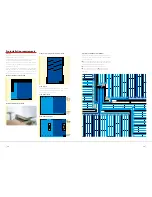
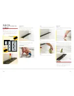
Blanking off the ZRU


Step 1:

Remove the under floor heating return pipe from ZRU and 
blank off the ZRU under floor heating return port with a short 
pipe with a blank end or a blanking plug. 

Filling the ZRU


Step 2:

Allow open ended under floor heating return pipe to drain into 
a bucket or hose.

Step 3:

Open the flow isolation valve to the ZRU. 

Step 4:

When uninterrupted flow is seen from the under floor heating 
return pipe, close the isolation valve and re-connect the under 
floor heating return pipe to the ZRU.  

Step 5:

Open all the valves. 

Step 6:

Vent the ZRU through the air vent and pump vent. 
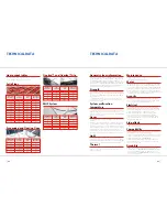


             Room packs

Open under 

floor heating 

flow isolation 

valve

Blank off 

under floor 

heating 

return to ZRU

Vent under floor 

heating system from 

under floor heating 

return pipe

  Type 

Solid Floor  

Overlay™ 

Overlay™ Lite 

  Area 

12m

2

 (

So12Z

)  

12m

2

 (

O12Z

12m

2

 (

OL12Z


20m

2

 (

So20Z

)  

20m

2

 (

O20Z

20m

2

 (

OL20Z


30m

2

 (

So30Z

)  

30m

2

 (

O30Z

30m

2

 (

OL30Z


A 5m

2

 Overlay™ Bathroom Pack (O5B) is controlled 

with a temperature limiting valve rather than the ZRU

A range of room packs containing all flooring 
and ZRU are available

Summary of Contents for Under Floor Heating Systems

Page 1: ...s Broomhouse Lane Edlington Doncaster DN12 1ES Tel 01709 770 000 Fax 01709 770 001 2410 London Road Mount Vernon Glasgow G32 8XZ Tel 0141 778 8822 Fax 0141 778 2703 Dromore Road Lurgan Craigavon Co Ar...

Page 2: ...revious printed copies will become out of date The latest version of our installation advice including a downloadable version of the current Technical Installation Guide can be found at our trade webs...

Page 3: ...xtensive back up service Technical representation available to discuss systems in general and particular projects www ufch com Technical Installation CD Specialist Technical Hotline on 01709 770000 En...

Page 4: ...he floor screed is required by Building Regulations Edge insulation also acts as an expansion joint Floating Floor When installed in floating floors Polyplumb pipe is simply pressed in to the pre form...

Page 5: ...r requires a bespoke design You then simply input data for each room providing floor type room size and control zones to calculate the required pack All packs have a single order code and include all...

Page 6: ...h when heated will reduce to 8 9 and cause only a very small amount of shrinkage The floor will re absorb some moisture when the heating is not operating and the moisture content will increase to 12 1...

Page 7: ...d around the perimeter of the room using staples so as to prevent possible risk of the panels lifting Preparing the pipe Step 4 You will need to remove the coil from the bag leaving the shrink wrap on...

Page 8: ...ted the screed cover can be applied Care should be taken to ensure that the screed is tightly compacted around the pipe to ensure that no voids are present The system should remain under pressure 6 ba...

Page 9: ...nder pressure whilst the flooring is laid Finishing The room can then be finished by fitting 18mm or 22mm tongue and groove sheets of chipboard glued on the edge over the floating floor system Mark th...

Page 10: ...hed downwards and away from the underside of the timber finished floor covering as this could lead to potential underperformance of the system Testing Step 4 Once the pipe circuits have been installed...

Page 11: ...These can be fixed directly through the spreader plate down in to the joists below It is important to indicate the position of pipework in areas where the additional fixing of items such as carpet gri...

Page 12: ...heir high output at relatively low flow temperatures Modular Heating Panels are ideal for maximising heat efficiency and lowering energy consumption In most installations it is not necessary to cover...

Page 13: ...should be selected The span is defined as the free space from wall to wall that needs to remain uninterrupted by trimmers or other services Ideally install MHP panels prior to other services whenever...

Page 14: ...omes into direct contact with it Always ensure that electrical cables are not in physical contact with the MHP panels using tape or a polythene strip Finishing Once you have connected your system up t...

Page 15: ...for heavyweight floor coverings such as ceramics or where the floor covering needs to be secured directly to the panel e g solid wood Overlay Lite is a high compressive strength lightweight insulated...

Page 16: ...is should be the first consideration for most projects The more structural nature of Overlay however makes it ideal for direct tiling or application of floor finishes which need to be fixed or screwed...

Page 17: ...mple of blanking in a bathroom Example of squaring off an irregular room plan Room layouts The following diagrams show some examples of room shapes pipe requirements and interruptions pillars hearths...

Page 18: ...wood floors they can be discretely screwed through the tongue and groove directly into the Overlay panel avoiding pipe circuitry to minimise movement in the floor covering If over boarding with 6mm p...

Page 19: ...r covering as normal It is advisable to mark out pipe positioning to avoid stapling pipes when fitting carpets 36 37 Overlay Lite for lightweight floor coverings Installation Laying end returns Step 1...

Page 20: ...stic hot water primary circuits To provide independent hydraulic control of the entire system it is important that the installation is designed as an S Plan or S Plan Plus configuration which allows f...

Page 21: ...d in under floor heating systems is less than that required for radiators or stored hot water If these other services are connected to the same boiler it will be necessary to control the water tempera...

Page 22: ...iring centre and slave units Available in two surface finishes and offers the following features Large touch screen display with high visibility blue LED backlight On screen display shows current stat...

Page 23: ...distribution pipe work Connection from nearest radiator 260mm 200mm Pump Pipe thermostat Heating return Heating flow Under floor heating flow Under floor heating return Thermostatic blending valve Pu...

Page 24: ...ible tap connectors for the simplest method of connection Close all under floor heating circuits except one by screwing down the blue caps and closing the isolating valves situated on top of the manif...

Page 25: ...resistant to the build up of scale Short term chlorination for disinfection of supply pipe work and normal levels of chlorine in UK domestic water supplies will not have an adverse effect on the integ...

Page 26: ...ng should be done with all switches on and room thermostats calling Fault finding complete Adjust pump speed and set flow rates in accordance with the system design data as provided NO NO Is the boile...

Page 27: ...Manufacturing quality assurance In accordance with BS ES ISO 9001 2000 BSI registered firm Certificate FM00318 Installation standard To follow the recommendations of BS5955 Part 8 2001 Plastic Pipewo...

Page 28: ...OR HEATING REQUIREMENTS Manifold Position s Please also indicate on drawing Floor Type Solid Suspended Floating MHP Overlay Overlay Lite Ground Floor 1st Floor 2nd Floor CONSTRUCTION DETAILS If NOT to...

Reviews: