


3. Module Pinout and Components
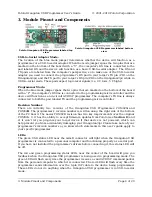
Pololu Orangutan USB Programmer labeled top
view
Pololu Orangutan USB Programmer labeled bottom
view
USB-to-Serial Adapter Mode:
The location of the blue mode jumper determines whether the device will function as a
programmer or a USB-to-serial adapter. When the mode jumper spans the two pins that are
marked on the bottom of the board with a “U”, the computer’s RX line is connected to the
pad labeled RX and the device will function as a basic USB-to-serial adapter. The RX and
TX pads are labeled from the computer’s perspective, so to make use of the USB-to-serial
adapter you need to connect the programmer’s RX pad to your target’s TX pin (PD1 on the
Orangutan/3pi) and the TX pad to your target’s RX pin (PD0 on the Orangutan/3pi) while in
USB-to-serial mode. These pads expect logic-level signals (i.e. 0 V lows, 5 V highs).
Programmer Mode:
When the blue mode jumper spans the two pins that are marked on the bottom of the board
with a “P”, the computer’s RX line is connected to the programming microcontroller and the
device will function as an in-circuit AVR ISP programmer. The computer’s TX line is always
connected to both the pad labeled TX and the programming microcontroller.
Revision Number
:
There are currently two versions of the Orangutan USB Programmer: PGM02
A
and
PGM02
B
. The programmer’s revision number is written along the right side of the bottom
of the PC board. The newer PGM02B revision has two key improvements over the original
PGM02A: 1) it has the ability to accept firmware updates from Pololu (see
) and
2) it won’t let you program your target device if that device is not powered, which can
help prevent you from accidentally damaging your Orangutan/3pi. Please take note of your
programmer’s revision number so you know which statements in this user’s guide apply to
your specific programmer.
LEDs:
The green USB status LED near the mini-B connector will light when the Orangutan USB
programmer is connected to a personal computer and functioning properly as a serial port.
If you have not installed the programmer’s drivers before connecting it, this status LED will
be off.
The red and green programming status LEDs near the center of the board will give you
feedback when the Orangutan USB programmer is being used in programming mode. The
green LED will flash every time the programmer receives a valid AVR ISP command packet
from the personal computer to which it is connected. The red LED will flash every time the
programmer sends information over the 6-pin ISP cable to the device being programmed.
These LEDs do not do anything when the Orangutan USB programmer is in USB-to-serial
mode.
Pololu Orangutan USB Programmer User's Guide
© 2001–2010 Pololu Corporation
3. Module Pinout and Components
Page 4 of 29


