


The First Use of
Polaris
9
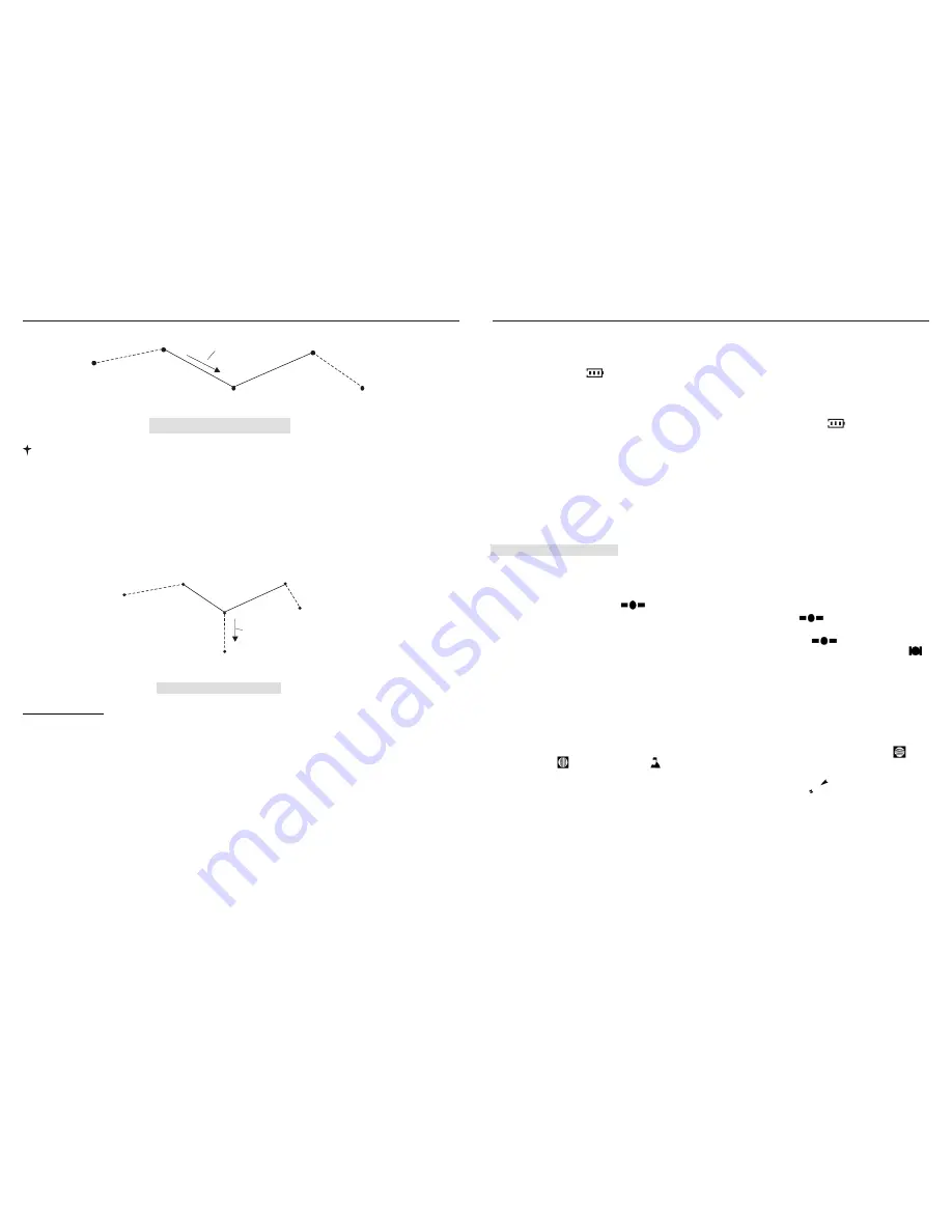
N-1
Pointer bearing
N+1
Home 0
N
Destination
Case 3: Forward-Tracking
Note 4: In the tracking forward state, system will stop
Marking
function. When user arrives at
Home N
,
Arriving Icon
will blink and arriving alert will start. At this time, all other button will
be disabled, until pressing '
OK'
button to stop it. Once the '
OK'
is pressed,
Home N
will increase
to
Home(N+1)
and the latitude, longitude and altitude windows display the geographic position
of (N+1) as current point, and the pointer will point to (N+2).
Case 4__ Renewed Navigation:
. In previous three cases, whenever a new destination is set,
Navigation Pointe
r will be forced to target the new destination, allowing user to go under the
guidance of the new bearing.
N-1
N+1
Home 0
N
Destination
Pointer bearing
New Destination
Case 4: Renewed Navigation
Digital Compass:
User should calibrate the digital compass before it start to work for the first time to use the
unit. After calibration, the digital compass keeps working, bearing the direction of the
North.
As
you turn around slowly with the Polaris in hand, you will see the
Bearing Arrow
of
Compass
and the Symbol
N
moving together, showing the direction of the
True North
as shown in figure
9.
16
POLARIS USER MANUAL
2. The battery icon pop up with its three rating signs cycling, signifying a charging
process underway. If the battery icon fails to appear, you should examine battery select
switch which locates on the left side of the inner body to make sure that the switch stay
on the upper side.
3. When batteries are charged to full, a period of about 5 hours, icon will start
blinking. User should remove the charging terminal from the charging port. If user fails
to remove the charging terminal from the charging port, the unit will automatically
reduce charging current to a very low value so that no damages will be caused to the
battery.
POLARIS USER MANUAL
To Charge batteries:
1. Pull the plastic cover from the charging port, insert adaptor's mini-USB terminal, then
connect the adaptor's another terminal to AC power main socket
1. Take the unit outside in an open area where there is no obstruction from a clear view of sky, press
POWER button to turn on the unit. You will see all the icons pop up on the screen for three seconds. After
the shown-all, then all data field will enter into zero state and the local time clock is running on.
2. With the GPS signal icon blinking, the unit is tracking the GPS signal to obtain the first
position fix, a process which will take a bout 2 to 3 minutes before the icon to stabilize.
3. As soon as the first position fix is been made, which is hinted by stable icon , the data field ,
and display respectively the latitude, longitude and altitude of your present standing. Several icons
appear, denoting the total number of satellite being tracked; GMT clock is wakened from the zero state
and synchronized with the time of satellite system.
4. To give a real meaning to local time clock, you should calibrate it with the GMT clock: press
UP
or
DOWN
button to highlight icon , then press
SET
button for three seconds. After this, local time clock
reflects the hour in user's local area, with its minute and second synchronized with GMT.
5. To activate the digital compass and give you proper explanation of the north, you should calibrate the
compass: Hold the unit on horizontal level, press '
SET
' button for three seconds, the Latitude Icon ,
Longitude Icon and Altitude Icon will start blinking for as long as 15 seconds. During this process,
turn with the unit at an angle of 360 degrees, then press and release '
SET
' button and turn in the opposite
rotation for another 360 degrees, then press '
SET
' button once to finish. Icon become active, with its
arrow kept pointing to the North.
At this moment, you have done all the preparation work. As you walk with the device holding
horizontally in hand and see latitude and longitude changing, speed data field showing the speed of your
movement.
‡J
‡E
‡C ‡D
‡P
‡K
‡J
‡L