0000104750/210616/B MobilePro | MobilePro/PTFE
EN - 7
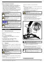
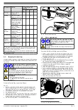
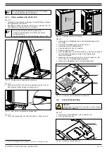
Fig. 4.2
A
Mounting of the working light cable
• Loosen the bolt M10 (A) at the bottom the unit. Continue
to turn the bolt until it gets fully loose
5
.
Fig. 4.3
±25 mm
(1 in.)
A
A
Bolt to unlock the front panel
• Push the front cover (A) down and remove it.
Fig. 4.4
±25 mm
(1 in.)
A
A
Disassembly of the front cover
• Remove the cover of the control panel (ref. Fig. 4.6B).
• Remove the cover caps at position B and C.
• Put a cable gland in both holes.
• Put the cable (A) through the cable glands.
• Tighten the cable glands.
• Connect the cable to the terminal block inside the control
panel in accordance with the separately supplied electrical
diagram.
5. The nut is locked to the front panel, so you cannot entirely remove it.
• Install the front cover of the unit (instructions of Fig. 4.3
and Fig. 4.4 in reverse order).
• Install the cover of the control panel.
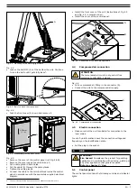
Fig. 4.5
A
B
C
Connection of the working light cable
4.4
Compressed air connection
aTTENTION
The compressed air must be dry and oil-free
according to ISO 8573-3 class 6.
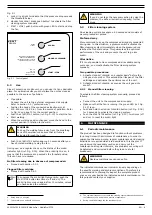
• Put a compressed air fitting in the connector (A).
• Connect the unit to the compressed air supply.
Fig. 4.6
A
B
Compressed air connection
4.5
Electric connection
• Make sure that the unit is suitable for connection to the
local mains.
You can find information about the connection voltage and
frequency on the identification plate.
• Put the plug in the socket.
5
USE
WaRNINg!
Fire hazard
! Do
not
use the product for polishing
applications in combination with grinding, welding or
any other application that generate sparks.
5.1
Control panel
The control panel contains the following controls and indicator
lights:
Summary of Contents for MOBILEPRO
Page 73: ......
Page 74: ...www plymovent com 0000104750 210616 B MobilePro MobilePro PTFE...


