


0507060400/010920/M DraftMax Basic | DraftMax Ultra
11
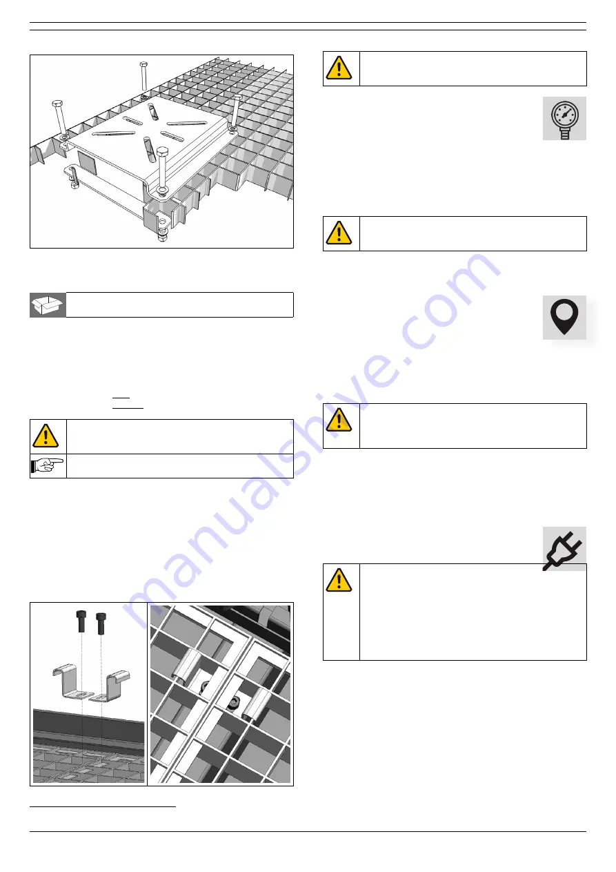
Fig. 4.22 Mounting of the bench vice mounting bracket
4.4.12 Wheel set
□
Swivel caster with brake (2)
□
Swivel caster without brake (3)
To install the wheet set, do the following.
• Lift the downdraft table with a fork-lift truck or pallet truck.
• Loosen and remove the 5 adjusting feet.
• Install the swivel casters instead;
- swivel casters with brake: left + right front corner
- swivel casters without brake: positions on the rear
ATTENTION
Turn the screw thread of the swivel casters in as
deep as possible.
By the use of the wheelset, the working height of
the downdraft table is fixed to 950 mm (37½ in.).
4.5
Work grid
To install the work grid, do the following.
• Loosen the ground bracket
3
from the downdraft table. Keep
the screws.
• Install the work grids.
• Put the ground bracket over both work grids.
• Attach it with the removed screws.
Fig. 4.1 Ground bracket (two-piece)
3. The ground bracket consists of two pieces
ATTENTION
It is necessary to apply the bracket to ground the
work grids.
4.6
Compressed air connection
(DraftMax Ultra only)
The downdraft table functions on compressed air
with a recommended working pressure of 5-8 bar
(72-115 psi). Make sure that the working pressure is between
these values (preferably at 5 bar/72 psi). If required, install a
pressure relief valve to prevent overpressure. If the pressure
is too high, the pressure relief valve of the system will be
opened, thus decreasing the pressure until the system
pressure has reached an appropriate level.
ATTENTION
The compressed air must be dry and oil-free
according to ISO 8573-3 class 6.
• Connect the downdraft table to compressed air (refer to
4.7
Positioning
You can move the downdraft table to its final
position with:
- a fork-lift truck (preferred way); or
- a pallet truck (in this case you must tilt the table); or
- cargo lashings lifted by a fork-lift truck (refer to Fig. I on
CAUTION
Do not position the product where it is exposed to
vibrations or heat radiation from heat sources.
Observe the earlier described ambient conditions.
• Put the downdraft table against the wall.
• If necessary:
Use the adjusting feet to put the table level and to adjust it
to the desired height (min. 920 mm - max. 970 mm/36-38
in.) (also refer to Fig. III on page 17).
4.8
Electric connection
CAUTION
Make sure that the product is suitable for connection
to the local mains. You can find information about
the connection voltage and frequency on the
identification plate.
The cables must be connected in conformance with
the local rules and regulations and can only be
carried out by well qualified and authorised
technicians.
You can connect the downdraft table to the mains by:
- a three-phase plug (grounded); or
- directly to the power supply
• Connect the mains cord to the mains.
4.8.1 Sense of rotation
To make sure that the sense of rotation of the fan is correct:
• Turn on the main switch.
• Push the ON button to switch on the fan.
•
Push the OFF button to switch off the fan.
• Wait 10 seconds.
• Open the left door.


