8
this button to see big picture of channel 10.while inputting numbers, this button is used as number
key of 0 .
12. Search/Menu: push this button to enter search menu, please refer search play in user
guideline for details. Long press this key to enter menu (need password), in menu setup, push
this key to quit current menu.
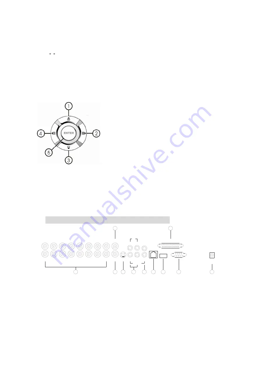
2.3 Channel Choosing Control Area
1. Four picture/up: Push this button to see full screen, re-push
this button to see the next channel. While selecting menu items,
push this button to move up the cursor.
2. Sixteen picture/right: Push this button to see sixteen
pictures display, re-push this button to see thirteen pictures.
While selecting menu items, push this button to move the cursor
rightward.
3. Big pictures/down: Push this button to see four pictures
display, re-push this button will display next four pictures. While
selecting menu items, push this button to move down the cursor.
4. Nine pictures/left: Push this button to see nine pictures display, re-push this button to see
eight pictures. While select menu items, push this button to move the cursor left ward.
5. Enter: While selecting menu items, push this button to select the item. While playing video,
push this button to pause the play, push play button to continue play.
3. REAR PANEL AND SYSTEM CONNECTION
IN
DEBUG
ALARM & RS485
USB
WAN
3
4
2
1
S VIDEO
OUT
OUT
CH16
CH8
CH15
CH7
CH14
CH6
CH13
CH5
CH12
CH4
CH11
CH3
CH10
CH2
CH9
CH1
OUT
OUT
DC 12V
INPUT
11
9
10
8
7
6
AUDIO
5
4
2
3
1
3.1 Back panel and connection terminals
The power cable and input, output signal terminals are all at the back of the machine, The
connection to monitor, camera etc equipments are all carried out through the terminals and
sockets on the back panel .the back view of the machine is illustrated as below.
Each part of the back panel is illustrated as below:
1.video input 1-16 2.main output 3.assistant monitor 4.S-VIDEO 5.audio input 6.audio output
7.net interface 8.USB port 10.debug port 11.power 9.Alarm and RS485port define:


