background image


VM Series Displays RS232 User Guide 

020-1359-00A 


Page | 20 


Video 

13.  Video Parameters


Use the following commands to get/set video parameters as defined below. 
 

13.1  Video Parameters Get 


Bytes 

Bytes Description 

Bits 

Description 

DATA[0] 

0x33 = Video Parameters- 
Get 


Command requests the display to report its 
current video parameters. 


Example: (Display Address 01) 


13.2  Video Parameters Report


Bytes


Bytes Description


Bits


Description


DATA[0] 

0x33 = Video Parameters- 
Report 


Command reports to the host controller the 
current video parameters of the display. 

DATA[1] 

Brightness 


0 to 100 (%) of the user selectable range of the 
display 

DATA[2] 

Color 


0 to 100 (%) of the user selectable range of the 
display 

DATA[3] 

Contrast 


0 to 100 (%) of the user selectable range of the 
display 

DATA[4] 

Sharpness 


0 to 100 (%) of the user selectable range of the 
display 

DATA[5] 

Tint (Hue) 


0 to 100 (%) of the user selectable range of the 
display 

DATA[6] 

Black Level 


0 to 100 (%) of the user selectable range of the 
display 

DATA[7] 

Gamma Selection 


0x01= Native, 0x02 = S gamma, 0x03 = 2.2, 
0x04 = 2.4 
0x05 = D-image(DICOM gamma) 


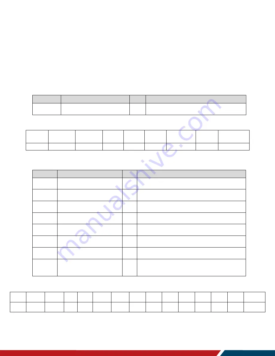
Example: Video parameters are set to 55 % (0x37) and Gamma Curve is set to 2.2 (Display Address 01)


Header 

Monitor 

ID 

Category 

Page 

Length 

Data 

Control 

Data[0] 

Data[1] 

Data[2] 

Data[3] 

Data[4] 

Data[5] 

Data[6] 

Data[7] 

Checksum 

0x21 

0x01 

0x00 

0x00 

0x0A 

0x01 

0x33 

0x37 

0x37 

0x37 

0x37 

0x37 

0x37 

0x03 

0x1B 


Header 

Monitor ID 

Category 

Code0 

Code1 

Length 

Data Control 

Data[0] 

Checksum 

0xA6 

0x01 

0x00 

0x00 

0x00 

0x03 

0x01 

0x33 

0x96 

Summary of Contents for VM55LX-U

Page 1: ...VM Series Displays RS232 User Guide 020 1359 00A RS232 User Guide Page 1 Planar VM Series Displays VM55LX U VM55LX X VM55MX X ...

Page 2: ...precaution has been taken in the preparation of this manual the Company shall not be liable for errors or omissions contained herein or for incidental or consequential damages in connection with the furnishing performance or use of this material Warranty and Service Plans Planar warranty and service plans will help you maximize your investment by providing great support display uptime and performa...

Page 3: ... Version Build Date Message Report 11 General 12 8 Power State 12 8 1 Power State Get 12 8 2 Power State Report 12 8 3 Power State Set 12 9 IR Remote Control Lock Functions 13 9 1 IR Remote Lock Status Get 13 9 2 IR Remote Lock Status Report 13 9 3 IR Remote Lock Status Set 14 9 4 Keypad Lock Status Get 14 9 5 Keypad Lock Status Report 14 9 6 Keypad Lock Status Set 15 10 Power State at Cold Start ...

Page 4: ...Color Parameters Report 23 13 9 Color Parameters Set 24 14 Zoom Mode 25 14 1 Zoom Mode Get 25 14 2 Zoom Mode Report 25 14 3 Zoom Mode Set 26 Audio 27 15 Volume 27 15 1 Volume Get 27 15 2 Volume Report 27 15 3 Volume Set 28 16 Audio Parameters 29 16 1 Audio Parameters Get 29 16 2 Audio Parameters Report 29 16 3 Audio Parameters Set 29 Miscellaneous 30 17 Operating Hours 30 17 1 Miscellaneous Info G...

Page 5: ...Table of Contents VM Series Displays RS232 User Guide 020 1359 00A Page 5 20 2 Tiling Report 33 20 3 Tiling Set 35 21 Tiling Preset 36 21 1 Tiling Preset Set 36 Command Summary 37 ...

Page 6: ...VM Series Displays RS232 User Guide 020 1359 00A Page 6 ...

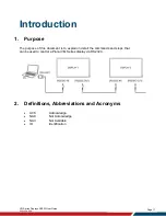
Page 7: ...on 1 Purpose The purpose of this document is to explain in detail the commands and steps that can be used to control a Planar VM Series display via RS232C 2 Definitions Abbreviations and Acronyms ACK Acknowledge NAK Not Acknowledge NAV Not Available ID Identification ...

Page 8: ... The Pin Assignments for DB9 male connector Male D Sub 9 Pin outside view Note Use a crossover cable null modem for connection to the host controller Planar VM Series displays use RXD TXD and GND pins for RS232C control For RS232C cable use the reverse type cable Pin Signal Remark 1 NC 2 RXD Input to LCD Monitor 3 TXD Output from LCD Monitor 4 NC 5 GND 6 NC 7 NC 8 NC 9 NC Frame GND ...

Page 9: ...ommand allowed the display performs the requested operation Note For LAN control the port number is 5000 5 Command Format The RS232 packet format Header Monitor ID Category Code0 Code1 Length Data Control Data 0 Data N Checksum In Detail Number of Field Name of Field Description Byte 1 Header Header 0xA6 Byte 2 Monitor ID Monitor ID Range 1 255 Signal Mode Display Address range from 1 to 255 Broad...

Page 10: ...yte6 Control 0x01 Byte7 Data 0 Copy the received Command code Byte8 Byte8 N 1 Data 1 Data N Returned data associated with command code Byte 8 N Checksum XOR of all byte in reply report packet except checksum itself Example ACK Reply Display Address 01 Header Monitor ID Category Page Length Control Data 0 Data 1 Checksum Description 0x21 0x01 0x00 0x00 0x04 0x01 0x00 0x00 0x25 Command is well execu...

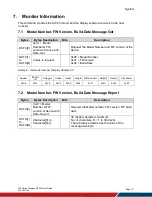
Page 11: ... to request 0x00 Model Number 0x01 FW version 0x02 Build Date Example Get model number Display Address 01 7 2 Model Number FW Version Build Date Message Report Bytes Bytes Description Bits Description DATA 0 0xA1 Model Number FW version of device with Date Report Request the Model number FW version FW build date DATA 1 to DATA N Character 0 to Character N 1 36 0x24 characters maximum No of charact...

Page 12: ...ytes Bytes Description Bits Description DATA 0 0x19 Power State Report Command reports power state DATA 1 Power State 0x01 Power Off 0x02 On Example Power State On Display Address 01 Header Monitor ID Category Page Length Data Control Data 0 Data 1 Checksum 0x21 0x01 0x00 0x00 0x04 0x01 0x19 0x02 0x3E 8 3 Power State Set Bytes Bytes Description Bits Description DATA 0 0x18 Power State Set Command ...

Page 13: ...l Data 0 Checksum 0xA6 0x01 0x00 0x00 0x00 0x03 0x01 0x1D 0xB8 9 2 IR Remote Lock Status Report Bytes Bytes Description Bits Description DATA 0 0x1D IR Remote Control Lock Status Report Report unlock all lock all lock all but power lock all but volume primary secondary status DATA 1 Status indicator byte for Remote Control 0x01 Unlock All 0x02 Lock All 0x03 Lock All but Power 0x04 Lock All but Vol...

Page 14: ...0xBF 9 4 Keypad Lock Status Get Bytes Bytes Description Bits Description DATA 0 0x1B Keypad Lock Status Get Set unlock all lock all lock all but power lock all but volume Primary Secondary status Example Display Address 01 Header Monitor ID Category Code0 Code1 Length Data Control Data 0 Checksum 0xA6 0x01 0x00 0x00 0x00 0x03 0x01 0x1B 0xBE 9 5 Keypad Lock Status Report Bytes Bytes Description Bit...

Page 15: ...ll lock all lock all but power lock all but Volume DATA 1 Status Indicator Byte for Keypad 0x01 Unlock All 0x02 Lock All 0x03 Lock All but Power 0x04 Lock All but Volume 0x07 Lock All except Power Volume Example Set Lock All on Keypad Display Address 01 Header Monitor ID Category Code0 Code1 Length Data Control Data 0 Data 1 Checksum 0xA6 0x01 0x00 0x00 0x00 0x04 0x01 0x1A 0x01 0xB9 ...

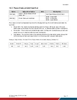
Page 16: ...or ID Category Code0 Code1 Length Data Control Data 0 Checksum 0xA6 0x01 0x00 0x00 0x00 0x03 0x01 0xA4 0x01 10 2 Power State at Cold Start Report Bytes Bytes Description Bits Description DATA 0 0xA4 Power State at Cold Start Report Report from Power state at Cold Start state DATA 1 Power State at Cold Start 0x00 Power Off 0x01 Forced On 0x02 Last Status Example Report status of Forced On for Power...

Page 17: ...ally switch to Power Off mode even if the last status was on whenever the main power turns on or resumes after a power interruption Forced On The monitor will automatically switch to Power On mode whenever the main power turns on or resumes after a power interruption Last Status The monitor will be automatically switch to the last status either Power Off or On whenever the main power turns on or r...

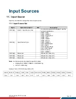
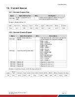
Page 18: ...Port 0x0B OPS 0x0D HDMI 1 0x0E DVI D 0x0F HDMI 3 0x10 BROWSER 0x11 CMS 0x16 Media Player 0x17 PDF Player 0x18 Custom 0x19 HDMI 4 DATA 2 Reserved Reserved value is 0 DATA 3 Reserved Reserved value is 0 DATA 4 Reserved Reserved value is 0 Note Certain sources only apply to specific models DisplayPort HDMI 3 HDMI 4 65 75 86 Only DVI D 43 55 Only Example Set on DVI D Display Address 01 Header Monitor ...

Page 19: ...ption Bits Description DATA 0 0xAD Current Source Report Command reports to the host controller the current input source used the display DATA 1 Input Source Type Number 0x05 VGA 0x06 HDMI 2 0x0A DisplayPort 0x0B OPS 0x0D HDMI 1 0x0E DVI D 0x0F HDMI 3 0x10 BROWSER 0x11 CMS 0x16 Media Player 0x17 PDF Player 0x18 Custom 0x19 HDMI 4 DATA 2 Reserved Reserved value is 0 DATA 3 Reserved Reserved value i...

Page 20: ...to 100 of the user selectable range of the display DATA 3 Contrast 0 to 100 of the user selectable range of the display DATA 4 Sharpness 0 to 100 of the user selectable range of the display DATA 5 Tint Hue 0 to 100 of the user selectable range of the display DATA 6 Black Level 0 to 100 of the user selectable range of the display DATA 7 Gamma Selection 0x01 Native 0x02 S gamma 0x03 2 2 0x04 2 4 0x0...

Page 21: ...play DATA 6 Black Level 0 to 100 of the user selectable range of the display DATA 7 Gamma Selection 0x01 Native 0x02 S gamma 0x03 2 2 0x04 2 4 0x05 D image DICOM gamma Example Set all video parameters to 0x37 55 Display Address 01 Header Monitor ID Category Code0 Code1 Length Data Control Data 0 Data 1 Data 2 Data 3 Data 4 Data 5 Data 6 Data 7 Checksum 0xA6 0x01 0x00 0x00 0x00 0x0A 0x01 0x32 0x37 ...

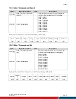
Page 22: ... 01 Header Monitor ID Category Page Length Data Control Data 0 Data 1 Checksum 0x21 0x01 0x00 0x00 0x04 0x01 0x35 0x01 0x10 13 6 Color Temperature Set Bytes Bytes Description Bits Description DATA 0 0x34 Color Temperature Set Command reports to the host controller the current color temperature of the display DATA 1 Color Temperature 0x00 User 1 0x01 Native 0x03 10000K 0x04 9300K 0x05 7500K 0x06 65...

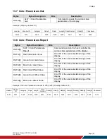
Page 23: ...display DATA 1 Red Color Gain Value 0 to 255 of the user selectable range of the display DATA 2 Green Color Gain Value 0 to 255 of the user selectable range of the display DATA 3 Blue Color Gain Value 0 to 255 of the user selectable range of the display DATA 4 Red Color Offset Value 0 to 255 of the user selectable range of the display DATA 5 Green Color Offset Value 0 to 255 of the user selectable...

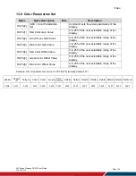
Page 24: ...lue Color Gain Value 0 to 255 of the user selectable range of the display DATA 4 Red Color Offset Value 0 to 255 of the user selectable range of the display DATA 5 Green Color Offset Value 0 to 255 of the user selectable range of the display DATA 6 Blue Color Offset Value 0 to 255 of the user selectable range of the display Example All color parameters are set to 255 0xFF Display Address 01 Header...

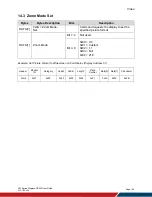
Page 25: ...1 Length Data Control Data 0 Checksum 0xA6 0x01 0x00 0x00 0x00 0x03 0x01 0x3B 0x9E 14 2 Zoom Mode Report Bytes Bytes Description Bits Description DATA 0 0x3B Zoom Mode Report Command report to the host controller the current picture format of the display DATA 1 Zoom Mode Bit 7 4 Not used Bit 3 0 0x00 4 3 0x01 Custom 0x02 Real 0x03 Full 0x04 21 9 Example Current Picture Format is Widescreen on Full...

Page 26: ... requests the display to set the specified picture format DATA 1 Zoom Mode Bit 7 4 Not used Bit 3 0 0x00 4 3 0x01 Custom 0x02 1 1 0x03 Full 0x04 21 9 Example Set Picture Format to Widescreen on Full Display Display Address 01 Header Monitor ID Category Code0 Code1 Length Data Control Data 0 Data 1 Checksum 0xA6 0x01 0x00 0x00 0x00 0x04 0x01 0x3A 0x03 0x9B ...

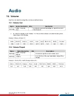
Page 27: ...e the system mute status of the display Example Display Address 01 Header Monitor ID Category Code0 Code1 Length Data Control Data 0 Checksum 0xA6 0x01 0x00 0x00 0x00 0x03 0x01 0x45 0xE0 15 2 Volume Report Bytes Bytes Description Bits Description DATA 0 0x45 Volume Report Command reports current volume level DATA 1 Volume 0 to 100 of the user selectable range of the display Example Volume 77 0x4D ...

Page 28: ...Command requests the display to set the specified volume parameters DATA 1 Volume 0 to 100 of the user selectable range of the display DATA 2 Audio Out Volume Level 0 to 100 of the user selectable range of the display Example Set the Display Volume to 77 0x4D Display Address 01 Header Monitor ID Category Code0 Code1 Length Data Control Data 0 Data 1 Data 1 Checksum 0xA6 0x01 0x00 0x00 0x00 0x04 0x...

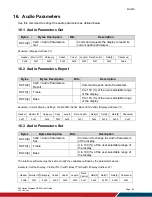
Page 29: ...y DATA 2 Bass 0 to 100 of the user selectable range of the display Example Current Display Settings Treble 80 0x50 Bass 93 0x5D Display Address 01 Header Monitor ID Category Page Length Data Control Data 0 Data 1 Data 2 Checksum 0x21 0x01 0x00 0x00 0x05 0x01 0x43 0x50 0x50 0x67 16 3 Audio Parameters Set Bytes Bytes Description Bits Description DATA 0 0x42 Audio Parameters Set Command to change the...

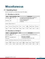
Page 30: ...play Address 01 Header Monitor ID Category Code0 Code1 Length Data Control Data 0 Data 1 Checksum 0xA6 0x01 0x00 0x00 0x00 0x04 0x01 0x0F 0x02 0xAF 17 2 Miscellaneous Info Report Bytes Bytes Description Bits Description DATA 0 0x0F Misc Info Report Command reports current Operating Hours DATA 1 to DATA 2 Operating Hours DATA 1 forms MSByte DATA 2 forms LSByte 16 bit wide operational hours value Ex...

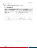
Page 31: ...scription Bits Description DATA 0 0x70 Auto Adjust Set Command requests the display to make auto adjustment on VGA input source DATA 1 Item 0x40 Auto Adjust All other values are reserved DATA 2 Reserved Default 0 Example Display Address 01 Header Monitor ID Category Code0 Code1 Length Data Control Data 0 Data 1 Data 2 Checksum 0xA6 0x01 0x00 0x00 0x00 0x05 0x01 0x70 0x40 0x00 0x93 ...

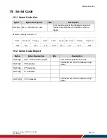
Page 32: ...n code 14 digits Example Display Address 01 Header Monitor ID Category Code0 Code1 Length Data Control Data 0 Checksum 0xA6 0x01 0x00 0x00 0x00 0x03 0x01 0x15 0xB0 19 2 Serial Code Report Bytes Bytes Description Bits Description DATA 0 0x15 Serial Code Report Command reports Serial Code DATA 1 1st Character Character acc ASCII character map HEX DATA 2 2nd Character DATA 3 3rd Character DATA 14 14t...

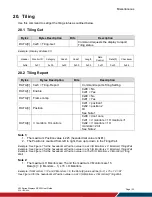
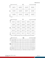
Page 33: ...Note 1 DATA 4 V monitors H monitors 0x00 don t care 0x01 V monitors 1 H monitors 1 0x02 V monitors 1 H monitors 2 till See Note 2 Note 1 1 The maximum Position value is 225 hexadecimal value is 0xE1 2 The Position is counted from left to right then up to down in the Tiling Wall Example See Figure 1 for the hexadecimal Position value in a 4x3 H Monitors x V Monitors Tiling Wall Example See Figure 2...

Page 34: ...isplays RS232 User Guide 020 1359 00A Page 34 Figure 1 Figure 2 The hexadecimal Position value in a 5x5 H Monitors x V Monitors Tiling Wall Figure 3 The hexadecimal Position value in a 15x10 H Monitors x V Monitors Tiling Wall ...

Page 35: ...nitors 1 0x02 V monitors 1 H monitors 2 till Example Set the Display to the following Tiling Enabled Yes Frame comp No Position 2 V Monitors 2 H monitors 3 Display Address 01 Header Monitor ID Category Code0 Code1 Length Data Control Data 0 Data 1 Data 2 Data 3 Data 4 Checksum 0xA6 0x01 0x00 0x00 0x00 0x07 0x01 0x22 0x00 0x00 0x02 0x08 0x89 Example Set the Display to the following Tiling Enabled Y...

Page 36: ...t Set Command requests the display to report Tiling status DATA 1 Action 0x00 Save 0x01 Recall DATA 2 Preset Preset number 0x00 Preset1 0x01 Preset2 till 0x09 Preset10 Example Save parameters of tiling into Preset 1 Display Address 01 Header Monitor ID Category Code0 Code1 Length Data Control Data 0 Data 1 Data 2 Checksum 0xA6 0x01 0x00 0x00 0x00 0x05 0x01 0x24 0x00 0x00 0x87 ...

Page 37: ...tart Set 0xA3 Current Source Get 0xAC Input Source Set 0xAD Auto Signal Detecting Get 0xAF Auto Signal Detecting Set 0xAE Video Parameters Get 0x33 Brightness etc Video Parameters Set 0x32 Brightness etc Color Temperature Get 0x35 Color Temperature Set 0x34 Color Parameters Get 0x37 Color Parameters Set 0x36 Zoom Mode Get 0x3B Zoom Mode Set 0x3A Volume Get 0x45 Volume Set 0x44 Audio Parameters Get...

Reviews: