background image

18

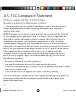
This device complies with Part 15 of the FCC Rules.

Operation is subject to the following two conditions: 

(1) This device may not cause harmful interference, and (2) this device must 
accept any interference received, including interference that may cause 
undesired operation.

NOTE: This equipment has been tested and found to comply with the limits for 
a Class B digital device, pursuant to Part 15 of the FCC Rules. These limits are 
designed to provide reasonable protection against harmful interference in 
a residential installation. This equipment generates, uses, and can radiate 
radio frequency energy and, if not installed and used in accordance with the 
instruction, may cause harmful interference to radio communications. However, 
there is no guarantee that interference will not occur in a particular installation. 
If this equipment does cause harmful interference to radio or television 
reception, which can be determined by turning the equipment off  and on, 
the user is encouraged to try to correct the interference by one or more of 
the following measures:

•  Reorient or relocate the receiving antenna. 

•  Increase the separation between the equipment and receiver. 

•  Connect the equipment into an outlet on a circuit diff erent from that to which 

the receiver is connected. 

•  Consult the dealer or an experienced radio/TV technical for help.

CAUTION: Changes or modifi cations to this equipment not expressly approved 
by the party responsible for compliance could void the user’s authority to 
operate the equipment.

U.S. FCC Compliance Statement

020-0509-00A GX3MP_2.indd   18

020-0509-00A GX3MP_2.indd   18

8/7/06   4:16:47 PM

8/7/06   4:16:47 PM

Summary of Contents for GX3MP

Page 1: ...GX3MP Display Reference Guide Windows XP Windows 2000 020 0509 00A GX3MP_2 indd 1 020 0509 00A GX3MP_2 indd 1 8 7 06 4 16 39 PM 8 7 06 4 16 39 PM...

Page 2: ...ical and electronic equipment EU countries require the use of separate recycling collection services Caution Read the accompanying text carefully for proper operation and maintenance of the display sy...

Page 3: ...m 4 Xeon AMD Athlon 64 K7 XP or compatible PCI Express x16 lane slot 50 MB hard disk space 256 MB RAM CD ROM drive Power supply 350 watts or greater Windows XP Service Pack 2 or Windows 2000 Service P...

Page 4: ...reas with sudden temperature changes and strong light sources Do not block the vents on the back of the display Do not remove the back cover or disassemble the display In locations where 240V outlets...

Page 5: ...formation about the status of the display DIN connector Drives power to the display via an 8 pin connector DVI connector Drives the data to the display 1 2 3 4 1 2 3 4 See page 12 for information on a...

Page 6: ...o reattach the cable cover align the hooks with the slots on the stand Press the cover into place A click sound signals a secure connection USB hub Use the integrated bus powered USB hub on the stand...

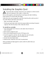
Page 7: ...tedly by touching the power supply or the metal surface of the computer chassis To install the controller 1 Turn off all peripherals Disconnect all cables from the back of your computer 2 Remove the c...

Page 8: ...of the DVI cable into DVI port 1 the bottom port on the installed graphics card 4 Plug the other end of the power cord into a grounded outlet 5 Power on your display first then the computer Use only t...

Page 9: ...DVI cable Use DVI port 1 the bottom port to connect a single display to the graphics card or to install the primary display of a dual configuration 020 0509 00A GX3MP_2 indd 9 020 0509 00A GX3MP_2 in...

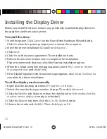
Page 10: ...the Express installation option 6 When the Setup complete message appears select Yes I want to restart my computer now and click Finish 7 If the Digital Signature Not Found message appears click Yes o...

Page 11: ...ness Do not adjust display brightness via the control panel To install the brightness control 1 Load the driver CD open the Brightness Control folder and run Setup exe 2 Click Next at the Welcome dial...

Page 12: ...side to adjust the viewing angle Height range Unfasten the stand lock at the top of the desk stand slide it to the left then adjust the height Orientation mode Turn the display 90 degrees counter clo...

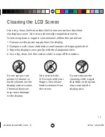
Page 13: ...gently with the dampened cloth 4 Use a dry clean lint free cotton cloth to wipe off the residue Cleaning the LCD Screen Do not touch the LCD screen with your fingers Skin oils are hard to remove from...

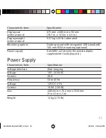
Page 14: ...al vertical Digital Video In DVI Rev 1 0 digital dual channel connector Display control DDC2B brightness contrast Display identification EDID read using DDC2B USB hub Universal Serial Bus USB Rev 1 1...

Page 15: ...ounting optional Power supply Ault MW122 Use only the power adapter supplied with the display unit Power Supply Characteristic Item Specification Voltage selection Auto ranging Voltage 100 240V AC Cur...

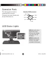
Page 16: ...onnector VCC 7 VCC 8 1 GND VCC 5 3 GND 2 GND VCC 6 4 GND LED Status Lights LED A describes the digital link status between the display controller and the interface LED B describes the display panel st...

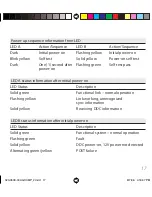
Page 17: ...l power on LED Status Description Solid green Functional link normal operation Flashing yellow Link working unrecognized sync information Solid yellow Receiving DDC information LED B status informatio...

Page 18: ...cations However there is no guarantee that interference will not occur in a particular installation If this equipment does cause harmful interference to radio or television reception which can be dete...

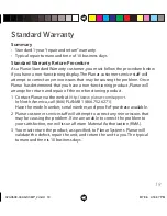
Page 19: ...non functioning product 1 Contact Planar via the web at http www planar com support In North America call 866 PLANAR1 866 752 6271 Have the model number serial number and proof of purchase available...

Page 20: ...tomer Support Visit www planar com Call 866 PLANAR1 Copyright 2006 Planar Systems Inc Planar is a registered trademark of Planar Systems Inc Technical information in this document is subject to change...

Reviews: