background image

– Motion 

Area 


The 

“Motion Detection” 

icon

 (Configuration>Event>General>Trigger) 

must be enabled when use 

this function. 

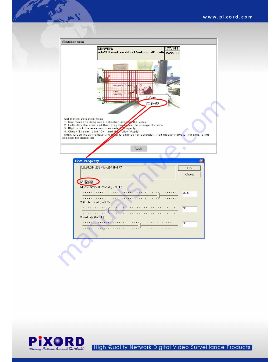
To set the area on video for motion detection: 

1.  Use Mouse to drag out a detection area on the video. 

2.  Left-click the area and drag the corner to change the size. 

3.  Right-click the area and select “Property”. 

4.  Check “Enable”, click “OK” and click “Apply”. 

Note: 

Green blocks indicate this area is enabled for detection. 

            Red blocks indicate this area is not enabled for detection. 

z


Apply:

 Saves the changes made. 

- 44 - 

Summary of Contents for P-423

Page 1: ...PiXORD MPEG 4 IR Network Camera P 423 426 428 User s Manual Version 1 4 Date 07 27 2007...

Page 2: ...OFTWARE INSTALLATION 13 3 3 NETWORK CONFIGURATION 14 Preparation before IP Assignment 14 Using IP Installer 14 4 USAGE OF WEB BASED USER INTERFACE 17 4 1 BROWSE LIVE VIDEO 18 Menu Language Selection 1...

Page 3: ...neral Settings 35 Dynamic DNS Settings 36 5 4 CONFIGURATION OF SYSTEM 39 System Information 39 Time Configuration 40 User Settings 41 Firmware Upgrade 42 5 5 CONFIGURATION OF EVENT 43 General Settings...

Page 4: ...illance systems that operate in both day and night conditions The MPEG 4 IR Network Camera is self contained Web Server Users could access the camera just like browsing website over Internet using sta...

Page 5: ...oviding Internet capability for remote access z Active X control for Microsoft Internet Explorer TM providing maximum performance z MPEG 4 and MJPEG video compression formats z Supports resolution up...

Page 6: ...tlet z PoE model The AC power is not necessary The camera will get the power from the Ethernet cable Please follow the below figure for the connection 2 Ethernet Connector Standard 10 100 Base T port...

Page 7: ...et hole E take the bracket F to fix on the screw hole H of camera G 2 Put the screw I through washer J and the bracket hole K take the bracket F to fix on the back side screw hole L on the IR Illumina...

Page 8: ...s LED Power status indicator Constant red when power is On 4 Network LED 3 4 1 2 5 z Network Link connected Constant red z Networks have activities Blink red z Data sent out from server Blink green z...

Page 9: ...2 3 Hardware Installation for P428 Part Description Dimension c Sun Shield f Bracket d Top Cover g Angle Adjustment Screw e Bottom Chassis h Window 8...

Page 10: ...ing and open the top cover with hexagon screw driver FIG 3 Loosen the screws on both sides of the supporter first use provided 1 4 20UNC screws black 2pcs to fix the camera on the supporter temporaril...

Page 11: ...video output of the camera FIG 7 Next use the provided 1 4 20UNC screws silver 4pcs to fix the housing on the bracket with hexagon screw driver FIG 8 4 Adjust the focus and iris of the lens on the cam...

Page 12: ...R1 toward MAX to higher the Infrared LED activation Lux level and vice versa 6 Loosen the angle adjustment screw on the bracket to turn the housing to the desired angle and then tighten the screw FIG...

Page 13: ...ngs such as video display and configuration z Macromedia Flash Player necessary for displaying some components of the Web UI The following are not necessary but may be used for added convenience z Rec...

Page 14: ...d configure network cameras and video servers on the LAN This utility is useful for conveniently configuring the network settings of the caera or for finding a device once the network settings have be...

Page 15: ...rk camera has a unique Ethernet address MAC address shown on the sticker of the camera as the serial number S N with 12 digits e g 000429 XXXXXX z z One final note although the IP Installer is able to...

Page 16: ...S N Serial Number 5 Double click the item to open the Property Page dialog box for the selected device or click the menu bar View Property 6 After filling in the properties click Synchronize button to...

Page 17: ...ng the Home Page at the first time with the Microsoft Internet Explorer TM you must temporarily lower your security settings to perform a one time only installation of the ActiveX component onto your...

Page 18: ...shown individually or in one of 4 split windows The status of the video stream Full Screen Maximizes to view the selected channels into full screen 1 3 Video stream from camera Local video source 4 2...

Page 19: ...hannel Selection The Video Channel item allows the users to select viewing 1 channel at a time or 4 channels at the same time CH1 displays the video stream of the MPEG 4 IR Network Camera CH2 4 displa...

Page 20: ...s for the selected channel will be displayed The settings can be setup in Configuration page On Off the Audio Select On or Off button beside Audio to enable or disable the audio from the selected chan...

Page 21: ...n be changed in Video Conference page z With factory defaults the recorded file will be saved in a folder named C MVS Recfile pppp CHx pppp The model number of the device x The number of the recorded...

Page 22: ...e channels at the same time To record the other channel just repeat the step 2 and 3 5 To stop the recording select the channel from the tab and then click Stop Rec button the REC message will disappe...

Page 23: ...ng You can change the settings for recording by clicking on Setting button in Location window z Reserve Space Set the total file space for the r Max File Le ecording z ngth Set the file space that a s...

Page 24: ...the remote device is a PTZ model or con lick Open PTZ button to open a PTZ control panel to control the device See 4 4 Control PTZ Devices for the instruction Manually Set Up Additional Camera urce fo...

Page 25: ...ce ort Enter a RTSP P Ent r a name for the ode Enter a PTZ mo z Product Type Select from MJPEG or MPEG4 Video Servers or IP Cameras Please refer to the origi of the device for a better description z A...

Page 26: ...ol The purpose of iris control is to adjust brightness on target It can be set as Auto Iris or Manual Iris z Iris open Click button to open the iris and brighten the picture z Iris close Click button...

Page 27: ...urces Set the video source for channel 2 to 4 using network connection IP Address If the video source is a PTZ device setup the parameters of the PTZ device here On Screen Display Set the text and loc...

Page 28: ...or the event and the action when an event is triggered Motion Area Decide the motion area where the event will be taken Email FTP Set the account information authorization for Email and FTP which will...

Page 29: ...o from the target actually we recommend disable the audio z Resolution There are 3 different resolutions to choose from D1 720x480 NTSC 720x576 PAL DVD Standard resolution SIF 352x240 NTSC 352x288 PAL...

Page 30: ...s recommended settings are QSIF FPS 15 256Kbps recommended settings are SIF FPS 10 512Kbps recommended settings are SIF FPS 15 768Kbps recommended settings are Full D1 FPS 10 1Mbps recommended setting...

Page 31: ...uality z TV Standard This is the read only information system will auto detect TV standard mode z Sequence Mode There are 2 different modes available I frames only I frames and P frames P frames or pr...

Page 32: ...s set to 60 which offers fair compression with a low likelihood of errors z Peak Bitrate This is used to set a maximum bitrate that can be achieved This is useful for setting bitrates between the valu...

Page 33: ...z Serial Mode Select the serial mode to RS232 or RS485 z COM port This the read only information and it will auto detect the COM port z Serial databits Serial baud rate Serial stopbits and Serial Pari...

Page 34: ...e type must match the external source provided z Rotation Rotation degrees run from 0 to 270 degrees for a permanent digital position 0 0 degree 1 90 degrees 2 180 degrees 3 270 degrees z PTZ Model En...

Page 35: ...z A Z 0 9 and Note The maximum display block area is 12X4 characters String length more than 12 will feed to next line and totally 4 lines available More than 4 lines will strip off z OSD Coordinate X...

Page 36: ...is connected This device traffic to Internet should go through Gateway if not setting this only Intranet LAN can be accessed z DNS Address 1 2 and 3 The DNS server IP address used for resolving domai...

Page 37: ...mera is located behind Dial up ADSL or IP sharing devices which does not have fix IP address then it s impossible to reach the network camera from Internet When the network camera enables the DDNS ser...

Page 38: ...t to 80 and inside the network camera Network Settings should set HTTP port with 8000 z Update Time Specify the network camera updated frequency in seconds and the default is 600 10 minutes in a range...

Page 39: ...255 0 2 Go into Virtual Server or Port Forwarding configuration page in the ADSL router set Port 80 to server IP 192 168 0 200 3 In Network Settings General page of the network camera configure the s...

Page 40: ...ion Useful as an administrative identifier Does not affect the operation of the device z Location Useful for identifying the position of the device Does not affect the operation of the device z Model...

Page 41: ...ate and time by clicking on the arrow button beside each field and select the value from the pull down list Click on Apply button to save the configuration z Time Zone Click on the arrow button and se...

Page 42: ...mited permission to operate the channels Delete User To remove a user select the user from the list and then click on Delete User button Note z Totally 10 users can be added z The first added user mus...

Page 43: ...irmware file under the name of flash bin z Once you have selected the file and clicked on Accept click on Update the message below shows up Click OK to confirm and proceed with the firmware upgrading...

Page 44: ...d FTP Image When an event is triggered the sanpshot of video will be send to the indicated FTP site Please set the FTP site in FTP Setting function Mail Image When an event is triggered the sanpshot o...

Page 45: ...ion 1 Use Mouse to drag out a detection area on the video 2 Left click the area and drag the corner to change the size 3 Right click the area and select Property 4 Check Enable click OK and click Appl...

Page 46: ...il authorization Account ID Password Enter the user name and password for the mail sender z FTP Setting The FTP Image icon Configuration Event General Active must be enabled when use this function Hos...

Page 47: ...ced Progressive Scanning Video Performance Up to 30 NTSC 25 PAL frames per second Network Interface 10 100 Base T Ethernet Protocols TCP UDP IP ICMP HTTP TFTP FTP Telnet SMTP DHCP NTP DNS DDNS RTSP RT...

Page 48: ...2 S N Ratio More than 48dB AGC Off More than 48dB AGC Off More than 48dB AGC Off Back Light Compensation ON OFF selectable ON OFF selectable ON OFF selectable Auto Electronic Shutter ON OFF selectable...

Page 49: ...n our case for Windows XP Enter DOS by Start All Programs Command Prompt Change to the folder where the latest flash bin exist Start ftp session by enter ftp Network camera s IP Address Enter root as...

Page 50: ...h 32 bytes of data Request timed out Request timed out Reply from 192 168 0 200 bytes 32 time 2ms TTL 255 Reply from 192 168 0 200 bytes 32 time 1ms TTL 255 Reply from 192 168 0 200 bytes 32 time 10ms...

Reviews: