3
8
CDJ-350
1
2
3
4
A
B
C
D
E
F
1
2
3
4
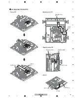
SLOTIN MECHA Section
(1) Disconnect the 27P FFC from control panel
section.
(2) Change the position of the LD SW (S951) on
the
C
N
CT Assy to "SHORT".
Note:
After work, connect the flexible cable on step (3),
then change the position to "OPE
N
".
(3) Disconnect the two flexible cables and
one
connector.
(4) Remove the four screws. (BPZ30P080FTB)
(5) Remove the four screws. (ABZ30P060FTC)
(6) Remove the MAI
N
PCB stay.
[1] MAIN PCB stay
2
1
C
N
CT Assy
27P FFC
3
4
4
3
4
4
5
5
5
5
Front
MAI
N
PCB stay
MAI
N
PCB stay
C
N
201
C
N
401
C
N
402
6
3
C
N
403
Summary of Contents for TRAKTOR PRO CDJ-350
Page 8: ...8 CDJ 350 1 2 3 4 A B C D E F 1 2 3 4 2 2 USABLE DISCS AND USB DEVICES ...
Page 9: ...9 CDJ 350 5 6 7 8 5 6 7 8 A B C D E F ...
Page 10: ...10 CDJ 350 1 2 3 4 A B C D E F 1 2 3 4 2 3 PANEL FACILITIES ...
Page 11: ...11 CDJ 350 5 6 7 8 5 6 7 8 A B C D E F ...
Page 71: ...71 CDJ 350 5 6 7 8 5 6 7 8 A B C D E F ...
Page 73: ...73 CDJ 350 5 6 7 8 5 6 7 8 A B C D E F H C 4 4 CN401 ...
Page 75: ...75 CDJ 350 5 6 7 8 5 6 7 8 A B C D E F H C 4 4 CN401 ...
Page 79: ...79 CDJ 350 5 6 7 8 5 6 7 8 A B C D E F ...
Page 93: ...93 CDJ 350 5 6 7 8 5 6 7 8 A B C D E F H H SMPS ASSY SIDE B SIDE B CN1 CN2 FOR CUXJ ...


