26
CDJ-350
1
2
3
4
A
B
C
D
E
F
1
2
3
4
[9] Basic operation
check of CPU/DSP
10.10
V
OLTAGES
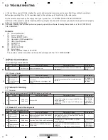
[8] Error Codes
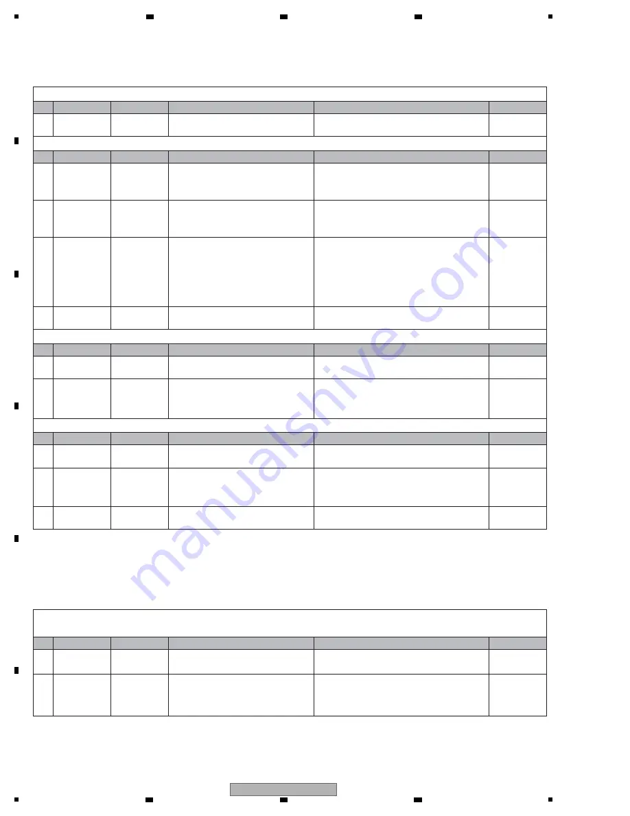
How to respond when an error code is displayed on the FL DISPLAY is described below.
E-6002: COMMUNICATION ERROR
• The program cannot be written in the DSP.
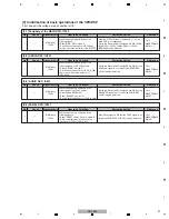
1
Power failure
MAI
N
Assy
Check the power voltages.
(
V
+3R3A,
V
+1R25)
If the voltage level is abnormal, IC402 or IC403
may be defective.
2
Defective part
MAI
N
Assy
Check if the AUDIO DSP (IC301) is
operating.
If the AUDIO DSP (IC301) is not operating, it may
be defective.
If the AUDIO DSP (IC301) is operating, the MAI
N
CPU (IC103) may be defective.
3
Power failure
MAI
N
Assy
Check the power voltages.
(
V
+7R6M,
V
+5R6M,
V
REF1R65,
V
+3R3S)
Check the mounting statuses of the regulator IC of
the power-supply section that produces that voltage
and its peripheral parts. If they are properly mounted,
then the parts may be defective.
V
REF1R65 is produced at the Servo IC (IC201).
If this voltage is not output, check the mounting
status of the IC201. If it is properly mounted, then the
part may be defective.
4.3 POWER SUPPLY
BLOCK DIAGRAM
4
Defective parts
If the symptom persists after the above
corrections,
DRI
V
ER IC(IC204) may be defective.
In-focus not possible
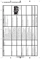
1
Defective pickup
MAI
N
Assy
Check the LD current and measure the
resistance value of the actuator.
Refer to the “5.3 Diagnosis of the Pickup Assy.”
5.3 Diagnosis of
the Pickup Assy
2
Power failure
MAI
N
Assy
Check the power voltages.
(
V
+7R6M,
V
+5R6M,
V
REF1R65,
V
+3R3S)
For any power-supply section that does not output
the voltage, check the mounting statuses of the
regulator IC and its peripheral parts. If they are
properly mounted, then the parts may be defective.
4.3 POWER SUPPLY
BLOCK DIAGRAM
N
o tracking close
3
—
Traverse
mechanism
Check that focusing is in. (If focusing is out,
tracking close is not possible.)
See “In-focus not possible” above.
[7-2] The drive does not work during Test Operation mode.
The LD does not emit light.
1
Defective pickup
Check the LD current and measure the
resistance value of the actuator.
See “5.3 Diagnosis of the Pickup Assy” for details.
5.3 Diagnosis of
the Pickup Assy
The spindle motor does not rotate.
1
Signal errors
MAI
N
Assy
Check that the DR
V
MUTE1 signal becomes
H after loading is completed.
If the signal is not normal, check the mounting
statuses of the DRI
V
ER IC (IC204) and MAI
N
CPU
(IC103) terminals. If they are properly mounted, then
the IC103 may be defective.
2
Signal errors
MAI
N
Assy
Check a SPI
N
signal.
(1.65
V
at the center. The voltage in the
start-up acceleration is around 3
V
.)
If the signal is not normal, check the mounting
statuses of the DRI
V
ER IC (IC204) and Servo CPU
(IC201) terminals. If they are properly mounted, then
the IC204 and IC201 may be defective.
—
—
—
—
—
—
No.
Cause
Diagnostics Point
Item to be Checked
Corrective Action
Reference
No.
Cause
Diagnostics Point
Item to be Checked
Corrective Action
Reference
No.
Cause
Diagnostics Point
Item to be Checked
Corrective Action
Reference
No.
Cause
Diagnostics Point
Item to be Checked
Corrective Action
Reference
No.
Cause
Diagnostics Point
Item to be Checked
Corrective Action
Reference
Summary of Contents for TRAKTOR PRO CDJ-350
Page 8: ...8 CDJ 350 1 2 3 4 A B C D E F 1 2 3 4 2 2 USABLE DISCS AND USB DEVICES ...
Page 9: ...9 CDJ 350 5 6 7 8 5 6 7 8 A B C D E F ...
Page 10: ...10 CDJ 350 1 2 3 4 A B C D E F 1 2 3 4 2 3 PANEL FACILITIES ...
Page 11: ...11 CDJ 350 5 6 7 8 5 6 7 8 A B C D E F ...
Page 71: ...71 CDJ 350 5 6 7 8 5 6 7 8 A B C D E F ...
Page 73: ...73 CDJ 350 5 6 7 8 5 6 7 8 A B C D E F H C 4 4 CN401 ...
Page 75: ...75 CDJ 350 5 6 7 8 5 6 7 8 A B C D E F H C 4 4 CN401 ...
Page 79: ...79 CDJ 350 5 6 7 8 5 6 7 8 A B C D E F ...
Page 93: ...93 CDJ 350 5 6 7 8 5 6 7 8 A B C D E F H H SMPS ASSY SIDE B SIDE B CN1 CN2 FOR CUXJ ...


