PDP-505MX
105
5
6
7
8
5
6
7
8
C
D
F
A
B
E
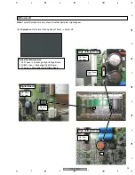
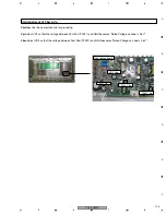
(4) Adjustment of Vbw & Vp
Caution:
Use the nearest chassis for grounding.
Vp:
Adjust VR1 so that the voltage between Test Pad (TP327) and GND becomes "Rated Voltage on Label
±
0.5V" .
Vbw:
Adjust VR2 so that the voltage between Test Pad (TP329) and GND becomes "Rated Voltage on Label
±
0.5V".
High Voltage Board
TP327 Vp
TP329 Vbw
VR2 Vbw
VR1 Vp
Summary of Contents for PDP-505MX
Page 7: ...PDP 505MX 7 5 6 7 8 5 6 7 8 C D F A B E ...
Page 21: ...PDP 505MX 21 5 6 7 8 5 6 7 8 C D F A B E ...
Page 46: ...PDP 505MX 46 1 2 3 4 1 2 3 4 C D F A B E Sensor Board IR Board Power Switch Board ...
Page 47: ...PDP 505MX 47 5 6 7 8 5 6 7 8 C D F A B E Button ...
Page 48: ...PDP 505MX 48 1 2 3 4 1 2 3 4 C D F A B E Audio Board ...
Page 49: ...PDP 505MX 49 5 6 7 8 5 6 7 8 C D F A B E ...
Page 50: ...PDP 505MX 50 1 2 3 4 1 2 3 4 C D F A B E PS250 PWR 500W ...


