44
MEH-P5350
7. GENERAL INFORMATION
7.1 DIAGNOSIS
7.1.1 TEST MODE
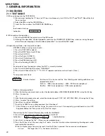
(1) When entering into the TEST MODE
1
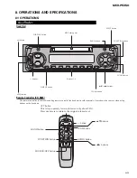
Pressing and holding the "4" key and "6" key simultaneously, turn ON the "ACC" and "B.UP" (Reset Start) at
the same time.
2
Select the MD using the [SOURCE] key.
3
Insert the Disc or press the POWER ON [BAND] key.
↓
Each mode starts up.
Indication
POWER ON
(2) When ending the operation
1
Press the [SOURCE] key again to end the MD mode.
2
Although the operation can be stopped by pressing the POWER OFF [BAND] key, when resuming the oper-
ation after once stopping it, take the above procedure 1 to turn off the MD mode.
(3) Operation methods under respective modes
♦
TESTMD (When making servo checks)
1
Press the TEST_MD mode [2].
2
Press the OFST Adjustment [2] key.
3
Press the LD_ON [1].
4
Press the Focus CLOSE [1].
5
Press the IV Adjustment [2].
6
Press the EF.B Adjustment [3].
7
Press the Tracking CLOSE [1].
↓
Tracing starts from the address where the P.UP is currently located.
8
Press the AGC Setting [3] to select "With BIAS".
9
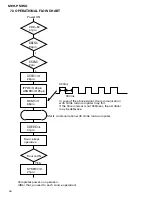
Press the AGC Execution [2]. "***11111111" appears and returns when it ends. [Disc+]
↓
Tracing movement starts.
Indication
XXXcXXs
(Cluster : Sector)
Positions of the cluster and the Disc (Starting and ending addresses are
approximate ones.)
PreDisc
FFE0 (inner periphery) ~ 0000 ~ 0900 (outer periphery)
RecDisc
0032 (inner periphery) ~ 0900 (outer periphery)
Address changing method
1
After the tracing movement ends, select the desired address (0003/0032/00b4/0500/0700) using the [6] key.
2
[Disc+] to execute.
or
1
After the tracing movement ends, select the desired jump (1T, 10T, 16T, 32T, FINE, FINE_LG) using the [4] key.
2
[Disc+] to enter the setting.
3
[trk+]/[trk-] to shift to FWD/REW.
** Do not use JUMP for any other purposes than the above!!
*** If the Pickup runs out of the Disc range, the serve will run out. Consequently, go into Search or turn OFF
the power before the Pickup runs out of the Disc range.
♦
Executing the Test Normal (Normal play under the TestMode)
1
Press the [3] key after each mode has started to start PLAY.
Indications
XXX
XX
XX
7-digit indication
Trk
Minutes
Seconds
2
[trk+]/[trk-] to change the "trk". (ff/rew are not workable here.)
3
Press the [3] key to call the occurring "err" code. (Use this function when determining the diagnosis when
making trouble shooting.)
When multiple err/ng are occurring, each time the [3] key is pressed, the newer error code appears.
err-n-xx
The larger the "n" is, the newer the error is.
Summary of Contents for MEH-P5350
Page 4: ...4 MEH P5350 2 2 EXTERIOR A B ...
Page 6: ...C D E 6 MEH P5350 2 3 MD MECHANISM MODULE ...
Page 16: ...KEY MICROCOMPUTER RESET 560 R47 2R7K 16 MEH P5350 1 2 3 4 1 2 3 4 D C B A 3 3 KEYBOARD UNIT B ...
Page 17: ...B LCD BACK LIGTH B A KEYBOARD UNIT CN831 17 MEH P5350 5 6 7 8 5 6 7 8 D C B A ...
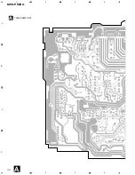
Page 30: ...30 MEH P5350 1 2 3 4 1 2 3 4 D C B A A A TUNER AMP UNIT ...
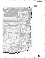
Page 31: ...31 MEH P5350 5 6 7 8 5 6 7 8 D C B A A SIDE B ...
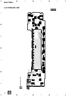
Page 33: ...33 MEH P5350 1 2 3 4 1 2 3 4 D C B A A CN831 B B SIDE B KEYBOARD UNIT ...
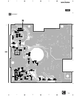
Page 35: ...IC Q D 35 MEH P5350 D C B A 1 2 3 4 1 2 3 4 C MD UNIT C SIDE B ...
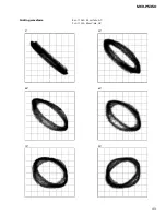
Page 43: ...43 MEH P5350 Grating waveform 45 0 75 60 30 90 Ech Xch 50mV div AC Fch Ych 50mV div AC ...

