FX-MG8667DVZT/EW
116
1
2
3
4
1
2
3
4
C
D
F
A
B
E
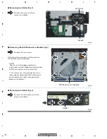
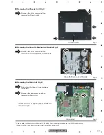
Fig.4
Holder
Cord Assy
-
Removing the Holder (Fig.4)
1
1
Fig.5
DVD Mechanism Module
-
Removing the DVD Mechanism Module (Fig.5)
Remove the four screws.
1
1
Remove the screw and then
remove the Holder.
1
1
1
Disconnect the connector and then remove
the DVD Mechanism Module.
Fig.6
Holder
-
Removing the Holder (Fig.6)
1
Remove the four screws and then
remove the Holder.
1
1
1
1
NOTE:
Take care not to engage code when
wire-processing the digital connecting code
of DVD mechanism during assembly.
(* For service use, this specification has a
long code for detachable MG4-mechanism
part enabling resin parts wire-processed
between the Holder. )
Summary of Contents for FX-MG8667DVZT/EW
Page 10: ...FX MG8667DVZT EW 10 1 2 3 4 1 2 3 4 C D F A B E 2 2 EXTERIOR 2 ...
Page 12: ...FX MG8667DVZT EW 12 1 2 3 4 1 2 3 4 C D F A B E 2 3 DVD MECHANISM MODULE G F E ...
Page 29: ...FX MG8667DVZT EW 29 5 6 7 8 5 6 7 8 C D F A B E A a A b A b 1 3 2 1R8K 3R3K 1K 1K 3 3 A LER ...
Page 34: ...FX MG8667DVZT EW 34 1 2 3 4 1 2 3 4 C D F A B E A a A b A b 2 3 1 3 A 1 3 A 1 3 A 1 3 A OR ...
Page 35: ...FX MG8667DVZT EW 35 5 6 7 8 5 6 7 8 C D F A B E A a A b A b 2 3 1 2 1 3 A 1 3 A 1 3 A 1 3 A ...
Page 49: ...FX MG8667DVZT EW 49 5 6 7 8 5 6 7 8 C D F A B E A a E b E a E b 1 2 E a 1 2 F ...
Page 53: ...FX MG8667DVZT EW 53 5 6 7 8 5 6 7 8 C D F A B E 2 2 E DVD CORE UNIT 2 2 2 2 E CN407 1 3 A ...
Page 73: ...FX MG8667DVZT EW 73 5 6 7 8 5 6 7 8 C D F A B E E SIDE A 60 70 80 90 100 110 120 ...
Page 74: ...FX MG8667DVZT EW 74 1 2 3 4 1 2 3 4 C D F A B E E E 6 70 80 90 100 110 120 DVD CORE UNIT ...
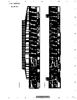
Page 131: ...FX MG8667DVZT EW 131 5 6 7 8 5 6 7 8 C D F A B E 7 2 2 DISPLAY CAW1867 SEGMENT COMMON ...

