FX-MG8667DVZT/EW
100
1
2
3
4
1
2
3
4
C
D
F
A
B
E
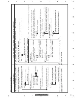
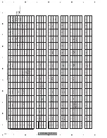
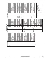
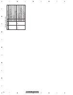
6.3 TEST MODE
-
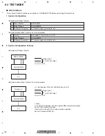
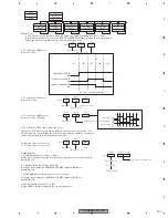
MG4 Test Mode
1. System Configuration
♦
System with Step-1 Master
1
2
3
2. System Configuration Scheme
♦
System with Step-1 Master
Image signal
SCI
H/U with MG4
PC
EMV or EMVN
AVC-LAN Step1
♦
System without Step-1 Master (H/U unit operation)
(
*
). Not needed, if the H/U with MG4 has an LCD.
Image signal
SCI
< Note >
In an H/U unit operation, you can operate MG4 test mode functions,
but no DVD’s normal functions.
If you want to check DVD’s normal function operation,
be sure to connect EMV (N).
H/U with MG4
PC
Display (
*
)
AVC-LAN Step1
H/U with MG4
Periphery Equipment
PC, power supply, serial cable, etc.
Target Device
Step-1 Master
EMV, EMVN
♦
System without Step-1 Master (H/U unit operation)
1
2
3
H/U with MG4
Periphery Equipment
PC, power supply, serial cable, etc.
Target Device
Display
Not needed, if the H/U has an LCD
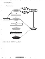
Note) Mount the MG4 mechanic assembly on FX-MG8567DVZT before performing this test mode.
Summary of Contents for FX-MG8667DVZT/EW
Page 10: ...FX MG8667DVZT EW 10 1 2 3 4 1 2 3 4 C D F A B E 2 2 EXTERIOR 2 ...
Page 12: ...FX MG8667DVZT EW 12 1 2 3 4 1 2 3 4 C D F A B E 2 3 DVD MECHANISM MODULE G F E ...
Page 29: ...FX MG8667DVZT EW 29 5 6 7 8 5 6 7 8 C D F A B E A a A b A b 1 3 2 1R8K 3R3K 1K 1K 3 3 A LER ...
Page 34: ...FX MG8667DVZT EW 34 1 2 3 4 1 2 3 4 C D F A B E A a A b A b 2 3 1 3 A 1 3 A 1 3 A 1 3 A OR ...
Page 35: ...FX MG8667DVZT EW 35 5 6 7 8 5 6 7 8 C D F A B E A a A b A b 2 3 1 2 1 3 A 1 3 A 1 3 A 1 3 A ...
Page 49: ...FX MG8667DVZT EW 49 5 6 7 8 5 6 7 8 C D F A B E A a E b E a E b 1 2 E a 1 2 F ...
Page 53: ...FX MG8667DVZT EW 53 5 6 7 8 5 6 7 8 C D F A B E 2 2 E DVD CORE UNIT 2 2 2 2 E CN407 1 3 A ...
Page 73: ...FX MG8667DVZT EW 73 5 6 7 8 5 6 7 8 C D F A B E E SIDE A 60 70 80 90 100 110 120 ...
Page 74: ...FX MG8667DVZT EW 74 1 2 3 4 1 2 3 4 C D F A B E E E 6 70 80 90 100 110 120 DVD CORE UNIT ...
Page 131: ...FX MG8667DVZT EW 131 5 6 7 8 5 6 7 8 C D F A B E 7 2 2 DISPLAY CAW1867 SEGMENT COMMON ...

