


76
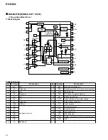
DV-646A
1
1
1
1
2
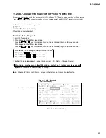
AVJB Assy
Connection Cable
for Service
[GGD1271]
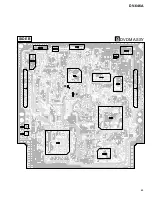
DVDM Assy
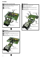
Styling of the Connection Cables
5
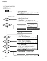
Diagnosis (2)
7
(
×
2)
3
1
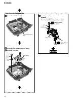
Remove the Rear Panel (Screws
×
15)
2
Remove the PCBs (Screws
×
14)
1
Connect two Connection Cables for Service (GGD1271)
between DVDM Assy and AVJB Assy.
2
3
Remove two screws.
Remove the DVDM Assy.
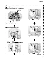
Diagnosis (1)
6
1
2
Arrange the Loading Mechanism Assy and the DVDM Assy
like the figure below.
Put in spacers under the Loading Mechanism Assy not to
rub the Clamper.
3
Playback with a test disc, and diagnose the DVDM Assy
and the other Assys.
DVDM Assy
Loading Mechanism Assy
Spacer
DVDM Assy
POWER SUPPLY Unit
AVJB Assy
KEYB Assy
PWSB Assy
FLIR Assy
Loading Mechanism Assy
Spacer
3
Arrange the Loading Mechanism Assy and the PCBs
like the figure below.
4
Playback with a test disc, and diagnose the AVJB Assy
and the other Assys.
Summary of Contents for DV-646A
Page 9: ...DV 646A 9 ...
Page 15: ...DV 646A 15 ...
Page 38: ...DV 646A 38 ...
Page 46: ...A B C D 1 2 3 4 1 2 3 4 46 DV 646A D 4 4 SCRB ASSY CN702 C VNP1838 A SIDE A SCRB ASSY D ...
Page 65: ...65 DV 646A DVDM ASSY B SIDE B TE FE ...
Page 101: ...101 DV 646A 8 PANEL FACILITIES AND SPECIFICATIONS 8 1 PANEL FACILITIES 8 1 1 Front Panel ...
Page 102: ...102 DV 646A 8 1 2 Remote Control ...
Page 103: ...103 DV 646A 8 1 3 Display Window ...