background image

DV-646A

14

A

B

C

D

1

2

3

4

1

2

3

4

H

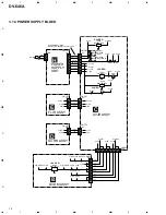
POWER
SUPPLY
UNIT

E

D

FLIR ASSY

C

AVJB ASSY

1

1

R439

V+12V

V+12V

V+6M

V+5E

V+5E

-27V

-27V

V+12V

V+5E

-27V

Q421

DV-646A
/WYXJ ONLY

IC421

PQ15RW11

EXCEPT
DV-646A
/WYXJ

DV-646A/WYXJ: GND
EXCEPT DV-646A/WYXJ: SW+3.3V

V+3V

V+2R5V

V+5V

+5V

V+5A

R440

R794 R790

R800

R793

LIVE

2

1

2

2

SW+3.3V

4

4

SW+5V

6

6

SW+12V

8

8

M+6V

10

10

EVER+5V

14

14

-27V

CN303

(14P)

CN2

CN101

(14P)

1

1

10

10

EVER+5V

V+12

14

14

-27V

CN301

(15P)

CN101

(15P)

SCRB ASSY

B

DVDM ASSY

+12V

+5V

V+12V

V+5V

14

3

2

5

7

8

10

9

12 14

12

5

+5V

+12V

CN702

(16P)

CN302

(40P)

CN101

(16P)

2

5

6V

5V

7

6V

8

3.3V

10

3.3V

9

12V

12

2.5V

14

2.5V

CN401

(40P)

NEUTRAL

AC IN

VREG

10V REG.

2.5V REG.

5V REG.

1.8V REG.

V+10A

V+5A

V+5V

SW+5V

V+5D

V+6M

V+5S

V+3V

V+12V

V+2R5V

V+6M

V+12V

IC422

NJM78M05FA

IC909

MM1561JF

IC301

BA25BCOFP

V+3D

V3VD

V18D

V18_ADSP1

V+3_18REG

V+12

V12M

V25V

V+2A

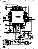
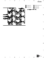
3.1.4 POWER SUPPLY BLOCK

Summary of Contents for DV-646A

Page 1: ... LIST 3 3 BLOCK DIAGRAM AND SCHEMATIC DIAGRAM 10 4 PCB CONNECTION DIAGRAM 39 5 PCB PARTS LIST 51 6 ADJUSTMENT 55 CONTENTS 7 GENERAL INFORMATION 61 7 1 DIAGNOSIS 61 7 1 1 ID NUMBER AND ID DATA SETTING 61 7 1 2 SELF DIAGNOSTIC FUNCTION OF PICKUP DEFECTIVE 63 7 1 3 TEST POINTS LOCATION 64 7 1 4 TEST MODE SCREEN DISPLAY 66 7 1 5 TROUBLE SHOOTING 70 7 1 6 ERROR CODE 71 7 1 7 DISASSEMBLY 75 7 2 IC 80 8 ...

Page 2: ... If you are not qualified to perform the repair of this product properly and safely you should not risk trying to do so and refer the repair to a qualified service technician Additional Laser Caution 1 Loading status detection switch S101 on the LOAB assy are detected by the microprocessor IC601 in the DVDM assy To permit the laser diode to oscillate it is required to set the loading status detect...

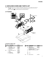
Page 3: ... PARTS LIST NOTES Parts marked by NSP are generally unavailable because they are not in our Master Spare Parts List The mark found on some component parts indicates the importance of the safety factor of the part Therefore when replacing be sure to use parts of identical designation Screws adjacent to mark on the product are used for disassembly NSP 11 Warranty Card ARY7022 12 Polyethylene Bag VHL...

Page 4: ...N A B C D D C E E A B Refer to 2 3 LOADING MECHANISM ASSY 34 32 10 32 30 9 12 5 17 33 31 33 28 30 29 29 11 16 1 2 3 20 24 21 22 25 26 4 19 29 29 23 14 13 15 6 30 30 30 30 7 D C F E G H B 27 18 31 33 33 29 29 29 29 8 29 29 29 29 29 ...

Page 5: ...6 12 PCB Support VEC2184 13 Foot VEC2185 14 PCB Holder VEC2215 NSP 15 Chassis VNA2160 16 Rear Panel VNA2309 17 Adapter27 L VNL1926 18 Adapter27 R VNL1927 19 Insulator VXA2424 20 DVD A V Plate VAM1118 21 Sub Plate VEC2205 22 FL Lens VEC2211 23 FL Filter VEC2213 24 Tray Panel VNK4819 25 Front Panel Assy VXA2447 26 Pioneer Name Plate VAM1109 27 Label VRW1872 NSP 28 ID Label VRW1877 29 Screw BBZ30P060...

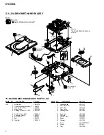
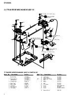
Page 6: ...rive Cam VNL1919 14 Gear Pulley VNL1921 15 Loading Gear VNL1922 16 Drive Gear VNL1923 17 SW Lever VNL1925 18 Clamper Plate VNE2251 19 Bridge VNE2252 20 Clamper VNL1924 21 Screw JGZ17P028FMC 22 Screw Z39 019 23 Tray VNL1920 A A To DVDM CN101 2 8 3 5 4 Refer to 2 4 TRAVERSE MECHANISM ASSY S 8 8 12 23 13 17 21 16 22 15 14 22 22 22 22 20 18 19 9 1 7 11 10 6 8 A Lubricating Oil GYA1001 Daifree GEM1036 ...

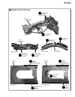
Page 7: ... Drive Cam No 13 Drive Cam No 23 Tray No 23 Tray Top View Rear View Top View Bottom View Daifree GEM1036 Daifree GEM1036 Daifree GEM1036 Daifree GEM1036 Daifree GEM1036 Side of the rib Inner side of a ditch Inner side of a ditch Lubricating Oil GYA1001 Lubricating Oil GYA1001 Inner side of a ditch Lubricating Oil GYA1001 Lubricating Oil GYA1001 Lubricating Oil GYA1001 ...

Page 8: ... 6 5 5 11 15 14 9 16 2 Screw Tight GYL1001 Silicone Adhesive GEM1037 Silicone Adhesive GEM1037 Silicone Adhesive GEM1037 17 Torque 0 12 0 01 N m 17 Torque 0 12 0 01 N m 17 Torque 0 12 0 01 N m 9 Joint Spring VNC1019 10 Support Spring VNC1020 NSP 11 Mechanism Chassis VNE2248 12 Slider VNL1811 13 Spacer VNL1913 14 Joint VNL1914 15 FFC Holder VNL1915 16 Screw BBZ20P050FZK 17 Screw OBA8009 18 Screw PM...

Page 9: ...DV 646A 9 ...

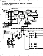
Page 10: ...ODER BY CHIP SCRUT IC702 GM71VS65803CLT 5 64M DRAM IC601 PD6345A SYSTEM CONTROL CPU IC101 PE5251A FL CONTROL V101 VAW1085 FL TUBE IC603 VYW1835 8M FLASH MEMORY 3 RF 54 170 111 107 RFO AIN ROMXA RD1 RD8 46 DSP RF 56 BH 57 PH 42 FE 35 4 57 60 63 66 149 150 152 155 158 159 48 TE 6 B1 7 B2 8 B3 9 B4 FDO 3 TDO 20 47 48 46 14 32 33 30 31 39 3 SPDO 21 112 33M BD0 BD7 CDDATA OUT V AD V 16M 44 48 3 3V to 5...

Page 11: ... 31 33 2 3 1 24 3 19 18 2 3 4 4 AO0 SDI1 SDO0 SDO1 SDO2 71 1 AO1 PD0 PD7 PD0 PD7 68 2 5 V V V V IC701 LA7138M 3IN 6OUT VIDEO AMP IC710 MM1508XN 6dB 75Ω DRIVER IC708 MM1506XN 6dB 75Ω DRIVER JA701 JA702 VIDEO OUT YELLOW VIDEO OUT S VIDEO OUT COMPOSITE C Y Y G B C Y Y C R C AMP 3 AMP 6 AMP 10 6 4 2 19 17 23 21 15 13 OUT IN 5 6 7 10 11 6 5 4 10 16 28 55 9 18 DACCLK DACCLK 36 DATA0 31 DATA1 33 DATA2 B ...

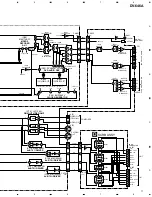
Page 12: ...C CS4392 3 24 14 15 18 19 IC905 TC7WH 157FU 1 AO0 IC906 TC74VHC 157FT 3 5 3 IC908 TC74VHC 157FT 4 JA501 IC331 AQE PD0274A 1 IC441 DAC CS4392 3 24 14 15 18 19 57 66 73 BD0 7 IC701 SCRUT PE5220A 4 149 159 1 DOUT1 IC906 TC74VHC 157FT 2 23 2 IC908 TC74VHC 157FT 4 JA501 IC331 AQE PD0274A 1 IC441 DAC CS4392 3 24 14 15 18 19 IC901 DSP XCA56367 10 4 JA501 IC331 AQE PD0274A 1 IC441 DAC CS4392 3 24 14 15 18...

Page 13: ...774BFP IC801 AV1 M65774BFP 4 IC491 TC74VHC153FT IC491 TC74VHC153FT IC491 TC74VHC153FT IC491 TC74VHC153FT IC491 TC74VHC153FT 7 DOUT DOUT0 ROMXA IC701 SCRUT PE5220A IC701 SCRUT PE5220A IC701 SCRUT PE5220A IC701 SCRUT PE5220A CDDATA 4 7 57 66 BD0 7 BD0 7 4 7 149 159 57 66 149 159 IC906 TC74VHC157FT 1 23 DOUT1 IC904 DIR LC89051V IC901 DSP XCA56367 IC901 DSP XCA56367 2 4 10 27 HADO 5 7 126 135 ASDATA0 ...

Page 14: ...SW 12V 8 8 M 6V 10 10 EVER 5V 14 14 27V CN303 14P CN2 CN101 14P 1 1 10 10 EVER 5V V 12 14 14 27V CN301 15P CN101 15P SCRB ASSY B DVDM ASSY 12V 5V V 12V V 5V 14 3 2 5 7 8 10 9 12 14 12 5 5V 12V CN702 16P CN302 40P CN101 16P 2 5 6V 5V 7 6V 8 3 3V 10 3 3V 9 12V 12 2 5V 14 2 5V CN401 40P NEUTRAL AC IN VREG 10V REG 2 5V REG 5V REG 1 8V REG V 10A V 5A V 5V SW 5V V 5D V 6M V 5S V 3V V 12V V 2R5V V 6M V 1...

Page 15: ...DV 646A 15 ...

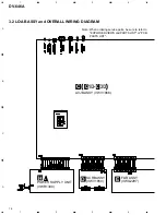
Page 16: ...te When ordering service parts be sure to refer to EXPLODED VIEWS and PARTS LIST or PCB PARTS LIST 3 2 LOAB ASSY and OVERALL WIRING DIAGRAM C 1 3 C 3 3 AVJB ASSY VWV1866 C POWER SUPPLY UNIT VWR1340 H SCRB ASSY VWV1850 D FLIR ASSY VWG2297 E ...

Page 17: ... ASSY VWG2306 G PICKUP ASSY S OXX8003 SPINDLE MOTOR VXX1088 STEPPING MOTOR CARRIAGE VXM1090 LOADING MOTOR ASSY VXX2505 TRAVERSE MECHANISM ASSY S VXX2782 LOADING MECHANISM ASSY VWT1188 RF SIGNAL ROUTE FOCUS SERVO LOOP LINE TRACKING SERVO LOOP LINE F RF T SLIDER SERVO LOOP LINE S RF RF RF F F F T F T F T T F S S S S ...

Page 18: ...DM ASSY 1 4 CN101 CN103 CN104 CN105 PICKUP ASSY CN601 A CARRIAGE MOTOR SPINDLE MOTOR ASSY 2 4 B 2 4 B 2 4 B 2 4 B 2 4 B 2 4 B 2 4 B 2 4 B 3 4 B B 1 4 DVDM ASSY VWS1470 RF IC FTS DRIVER RF F F T F F F T T RF RF F T T F F T T S S S S S A F T V V 1 2 4 ...

Page 19: ... B 3 4 B 3 4 B 2 4 B 2 4 B 2 4 B 3 4 B 3 4 B 2 4 B 3 4 B 2 4 B SERVO DSP SPDL DRV IC RF SIGNAL ROUTE AUDIO DATA SIGNAL ROUTE FOCUS SERVO LOOP LINE TRACKING SERVO LOOP LINE SLIDER SERVO LOOP LINE F AD RF RF VIDEO SIGNAL ROUTE V RF AUDIO SIGNAL ROUTE A T S T F T F F T F T A AD AD V V 5 6 8 9 11 10 7 ...

Page 20: ...2 3 4 3 4 DVDM ASSY 2 4 2 4 B VYW1835 3 4 B 3 4 B 3 4 B 1 4 B 3 4 B 1 4 B 3 4 B 3 4 B 1 4 B 1 4 B 1 4 B 1 4 B 1 4 B 1 4 B 1 4 B 1 4 B 1 4 B 4 4 B 3 4 B 4 4 B 3 4 B 3 4 B 4 4 B 1 4 B 3 4 B B 2 4 DVDM ASSY VWS1470 PGM FLASH MEMORY FR ...

Page 21: ...box CN501 CN401 10P 10P CN601 C2 3 CN302 C1 3 1 4 B 4 4 B 3 4 B 3 4 B 3 4 B 1 4 B 2 4 4 4 B 3 4 B 3 4 B 3 4 B 3 4 B 3 4 B 4 4 B 4 4 B 4 4 B 4 4 B 4 4 B 3 4 B CLOCK GENERATOR 3 3 5V CONVERTOR 5 3 3V CONVERTOR D AUDIO DIGITAL SIGNAL ROUTE D D D D D D D VD VIDEO DATA SIGNAL ROUTE VD VD D ...

Page 22: ... A B C D 1 2 3 4 1 2 3 4 3 5 DVDM ASSY 3 4 3 4 B 4 4 B 2 4 B 2 4 4 4 B 2 4 B 2 4 B 1 4 B 1 4 B 1 4 B 1 4 B 1 4 B 2 4 B 4 4 B 1 4 B 2 4 B 1 4 B 2 4 B 4 4 B B 3 4 DVDM ASSY VWS1470 64M DRAM SCRUT VD V V VD V AD AD ...

Page 23: ... 7 8 3 4 B 2 4 B 2 4 B 2 4 B 4 4 B 2 4 4 4 B 4 4 B 4 4 B 2 4 B 2 4 B 1 4 B 16M SDRAM AV 1 AD VD RF VIDEO SIGNAL ROUTE V VIDEO DATA SIGNAL ROUTE AUDIO DATASIGNAL ROUTE D AUDIO DIGITAL SIGNAL ROUTE AUDIO SIGNAL ROUTE VD VD VD D D D VD ...

Page 24: ... 22 2 4 B 2 4 B 2 4 B 3 4 B 2 4 B 2 4 B 3 4 B 3 4 B 2 4 B 2 4 B 2 4 B 2 4 B 2 4 B 2 4 B 3 4 B 3 4 B 2 4 B 3 4 B 3 4 B 3 4 B 2 4 B 3 4 B DVD AUDIO DSP B 4 4 DVDM ASSY VWS1470 D D D D D D D D D D D D D D D D D D D D D 3 6 DVDM ASSY 4 4 4 4 B ...

Page 25: ...DV 646A 25 A B C D 5 6 7 8 5 6 7 8 4 4 B The power supply is shown with the marked box 2 4 B 1 8V REGULATOR D AUDIO DIGITAL SIGNAL ROUTE ...

Page 26: ...DV 646A 26 A B C D 1 2 3 4 1 2 3 4 1 3 C C 1 3 AVJB ASSY VWV1866 CN401 D2 4 CN101 H CN101 E D D D D D D D D D D 3 7 AVJB ASSY 1 3 ...

Page 27: ... C The power supply is shown with the marked box R1042 R1041 R1043 R1044 R1045 GNDD GNDD R1047 R1046 R1048 R1049 R1050 GNDD GNDD R1052 R1051 R1053 R1054 R1055 GNDD GNDD 3 3 C D D D D D D D D D D AUDIO DIGITAL SIGNAL ROUTE AUDIO SIGNAL ROUTE ...

Page 28: ...DV 646A 28 A B C D 1 2 3 4 1 2 3 4 2 3 C CN601 CN501 B 2 4 C 2 3 AVJB ASSY VWV1866 3 3 C VIDEO ENCODER 3 3 C 1 3 C R B C V G Y VD VD 1 2 5 4 3 6 3 8 AVJB ASSY 2 3 ...

Page 29: ...SA1037K Q602 2SA1037K Q603 2SA1037K Q604 2SA1037K Q605 2SA1037K Q606 2SA1037K 3 3 C 3 3 C G B R G R B G B R V V C Y C Y C Y V V SIGNAL ROUTE Y SIGNAL ROUTE C SIGNAL ROUTE VD G R VIDEO DATA SIGNAL ROUTE R SIGNAL ROUTE B G SIGNAL ROUTE B SIGNAL ROUTE ...

Page 30: ... 2 3 4 Q701 2SA1037K Q702 2SA1037K Q703 2SA1037K Q774 2SA1037K Q771 2SA1037K Q768 2SA1037K 2 3 C 2 3 C C 3 3 AVJB ASSY VWV1866 6dB 75Ω DRIVER 6dB 75Ω DRIVER V V C V G B R C Y V C C Y V Y G G B R C Y V R B R 3 9 AVJB ASSY 3 3 3 3 C ...

Page 31: ... 3 C 2 3 C 2 3 C 3 IN 6 OUT VIDEO AMP 6dB 75Ω SW DRIVER 6dB 75Ω SW DRIVER C Y V V V V V C C Y Y V V SIGNAL ROUTE Y SIGNAL ROUTE C SIGNAL ROUTE AUDIO SIGNAL ROUTE Y V R C R Y V SIGNAL ROUTE R C SIGNAL ROUTE G R SIGNAL ROUTE G SIGNAL ROUTE B B SIGNAL ROUTE R C C C V R C Y V V Y Y C Y C Y V B G R C ...

Page 32: ...D 1 2 3 4 1 2 3 4 Q401 2SC2412K Q401 2SC2412K Q401 2SC2412K Q401 2SC2412K Q401 2SC2412K Q401 2SC2412K Q403 2SA1037K Q403 2SA1037K CN101 CN702 C3 3 SCRB ASSY VWV1850 D B B G B G G R C R C Y V Y V Y V Y V 3 10 SCRB ASSY D ...

Page 33: ...d box 0 1 R C R C R C R C B B G B B B G G G G B G B B G G Y V Y V Y V Y V Y V Y V Y V Y V Y V Y V Y V Y V R C B G Y V Y V R C R C R C V Y R C Y V Y V Y V V SIGNAL ROUTE Y SIGNAL ROUTE AUDIO SIGNAL ROUTE Y V R C Y V SIGNAL ROUTE R C SIGNAL ROUTE G G SIGNAL ROUTE B B SIGNAL ROUTE ...

Page 34: ...DV 646A 34 A B C D 1 2 3 4 1 2 3 4 FLIR ASSY VWG2297 E FL CONTROL MICROCOMPUTER 3 11 FLIR PWSB and KEYB ASSYS E ...

Page 35: ...er supply is shown with the marked box CN251 CN103 CN201 CN102 CN101 KEYB ASSY VWG2306 G PWSB ASSY VWG2307 F CN301 C1 3 KEYB ASSY S251 0 OPEN CLOSE S252 3 PLAY S253 4 1 S254 4 1 S255 7 STOP S256 8 PAUSE PWSB ASSY S201 POWER STANDBY ON S202 FL DIMMER ...

Page 36: ...1 C201 R24 R25 R11 R22 D8 D4 PC1 D6 R9 Q20 Q1 Q2 PC2 PC1 IC201 R7 R6 R5 R19 R1 D14 D13 T1 D11 D12 D81 D82 D83 R84 R85 Q81 R82 R83 C81 L1 D105 D104 C107 D103 D102 P101 AEK7063 P102 AEK7066 C105 C106 C410 L101 C109 Q411 Q410 D111 D407 D112 D405 D406 D107 D301 D108 D109 D304 C112 PC2 C111 C411 IC103 IC102 C301 C303 800mA 1 6A NOTE OF SPARE PARTS IN POWER SUPPLY SYPS UNIT In case of repairing use the ...

Page 37: ...41 C output V 0 2V div H 10µsec div 4 IC601 pin 36 R output V 0 2V div H 20µsec div 5 IC601 pin 40 G output V 0 2V div H 20µsec div 6 IC601 pin 37 B output V 0 2V div H 20µsec div 8 Foot of R261 FPWM V 1V div H 5msec div 9 Foot of R262 VPWM V 1V div H 5msec div 10 Foot of R263 PPWM V 1V div H 5msec div 11 Foot of R264 RPWM V 1V div H 5msec div GND GND GND GND DVDM ASSY B AVJB ASSY C WAVEFORMS Note...

Page 38: ...DV 646A 38 ...

Page 39: ...ts mounted on this PCB include all necessary parts for several destinations For further information for respective destinations be sure to check with the schematic diagram 4 View point of PCB diagrams Symbol In PCB Diagrams Symbol In Schematic Diagrams Part Name B C E D D G G S S B C E B C E D G S B C E B C E B C E Transistor Transistor with resistor Field effect transistor Resistor array 3 termin...

Page 40: ...VDM ASSY VNP1825 A DVDM ASSY B SIDE A IC401 IC911 IC912 IC901 Q101 Q115 Q116 Q117 Q111 Q118 IC281 IC351 IC532 IC291 IC201 IC904 IC302 IC802 IC804 IC803 IC261 IC210 IC702 IC601 IC606 IC491 IC211 Q571 Q542 Q112 Q543 Q292 Q241 Q141 Q107 Q291 Q102 ...

Page 41: ...SSY CN601 A CN302 C CN601 C STEPPING MOTOR CARRIAGE VNP1825 A DVDM ASSY B SIDE B IC251 Q103 Q109 Q108 Q130 IC903 IC909 IC910 IC902 IC913 IC907 Q142 Q113 Q281 Q271 Q210 Q106 Q601 IC306 IC305 IC701 IC299 IC603 IC801 IC303 IC304 IC101 IC271 IC905 IC608 IC612 Q161 ...

Page 42: ...1 Q421 Q554 Q558 Q504 Q508 Q452 Q449 Q444 Q446 Q445 Q447 IC441 IC333 IC501 IC351 IC551 IC371 IC334 IC352 IC353 IC302 IC361 IC312 IC314 IC316 IC311 IC313 IC315 IC317 IC362 IC422 IC332 Q552 Q556 Q502 Q506 Q442 Q443 Q441 CN101 E CN101 H CN401 B AVJB ASSY C 4 3 AVJB ASSY C ...

Page 43: ...IC791 IC701 Q704 Q601 Q605 Q604 VR602 VR601 VR951 IC601 IC905 IC901 IC902 IC903 IC1000 Q982 Q983 Q981 Q1000 Q603 Q602 Q601 Q701 Q702 Q703 IC710 IC708 IC706 IC707 IC705 IC703 IC709 IC702 IC704 Q1002 Q705 Q1001 CN101 D CN501 B VNP1839 A SIDE A C ...

Page 44: ...A B C D 1 2 3 4 1 2 3 4 44 DV 646A Q45 Q450 Q774 Q771 Q768 Q706 Q707 Q708 IC921 VNP1839 A SIDE B C ...

Page 45: ...A B C D 5 6 7 8 5 6 7 8 45 DV 646A Q457 Q451 Q448 Q456 Q507 Q505 Q501 Q503 Q557 Q555 Q551 Q553 Q450 IC331 IC301 AVJB ASSY C C ...

Page 46: ...A B C D 1 2 3 4 1 2 3 4 46 DV 646A D 4 4 SCRB ASSY CN702 C VNP1838 A SIDE A SCRB ASSY D ...

Page 47: ...A B C D 1 2 3 4 1 2 3 4 47 DV 646A D VNP1838 A SIDE B SCRB ASSY D Q212 Q211 Q231 Q231 Q313 Q311 Q401 Q403 Q312 ...

Page 48: ...A B C D 1 2 3 4 1 2 3 4 48 DV 646A 4 5 FLIR ASSY CN201 F CN301 C CN251 G SIDE A SIDE B FLIR ASSY E VNP1839 A IC103 IC111 IC101 Q101 E ...

Page 49: ...A B C D 1 2 3 4 1 2 3 4 49 DV 646A 4 6 PWSB and KEYB ASSYS CN103 E CN102 E SIDE A SIDE B SIDE A SIDE B PWSB ASSY F VNP1839 A KEYB ASSY G VNP1839 A G F ...

Page 50: ...A B C D 1 2 3 4 1 2 3 4 50 DV 646A POWER SUPPLY UNIT H CN303 C AC IN SIDE A Q411 Q410 IC102 IC103 VR 201 IC201 Q20 Q71 Q2 Q1 Q412 Q402 Q401 H 4 7 POWER SUPPLY UNIT ...

Page 51: ...ERS CN602 CONNECTOR S2B PH K CN601 CONNECTOR S5B PH K PRINTED CIRCUIT BORD VNP1836 DVDM ASSY SEMICONDUCTORS IC261 IC281 IC302 BA4510F IC251 BA6664FM IC481 BU2288FV IC702 GM71VS65803CLT 5 IC802 HY57V161610DTC 8 IC902 IS61LV6416 12T IC903 IS63LV1024 12T IC101 LA9701M IC201 LC78652W IC904 LC89051V IC351 M56788AFP IC801 M65774BFP IC909 MM1561JF IC601 PD6345A IC701 PE5220A IC111 IC271 TC74HC4053AFT IC6...

Page 52: ...SRYF105Z10 C882 C883 C888 C894 C898 CKSRYF105Z10 C901 C903 C905 C908 CKSRYF105Z10 C911 C913 C918 C920 CKSRYF105Z10 C923 C926 C929 C933 C934 CKSRYF105Z10 C938 C942 C945 C948 C949 CKSRYF105Z10 C956 C957 C965 C974 C980 CKSRYF105Z10 C986 C988 C991 C993 C995 CKSRYF105Z10 C403 100µF 6 3V VCH1194 C472 C700 C801 150µF 4V VCH1195 C367 33µF 16V VCH1197 RESISTORS R800 R895 RAB4C0R0J R543 R545 R631 R714 R744 ...

Page 53: ...F105Z10 C420 C421 C451 C506 C556 CKSRYF224Z16 C461 C464 C481 C484 100µF VCH1192 RESISTORS R461 R475 R481 R495 R511 RN1 16SE1202D R521 R532 R535 R561 R571 RN1 16SE1202D R582 R585 RN1 16SE1202D R464 R467 R484 R487 R514 RN1 16SE1502D R517 R524 R527 R564 R567 RN1 16SE1502D R574 R577 RN1 16SE1502D R462 R465 R482 R485 R512 RN1 16SE2201D R515 R522 R525 R562 R565 RN1 16SE2201D R572 R575 RN1 16SE2201D R474...

Page 54: ...RS All Resistors RS1 16S J OTHERS CN103 CONNECTOR 4P 04R FJ CN102 CONNECTOR 7P 07R FJ CN101 15P CONNECTOR 15R 1 25FJ V101 FL TUBE VAW1065 FL HOLDER VNK4748 X101 5MHz VSS1142 PWSB ASSY SEMICONDUCTORS D202 SLR 56DC NPQ SWITCHES AND RELAYS S201 S202 ASG7013 RESISTORS All Resistors RS1 16S J OTHERS CN201 CONNECTOR 7P 07P FJ KEYB ASSY SWITCHES AND RELAYS S251 S256 ASG7013 RESISTORS All Resistors RS1 16...

Page 55: ...L1001 Screwdriver medium 6 ADJUSTMENT 6 1 ADJUSTMENT ITEMS AND LOCATION Adjustment Items Mechanism Part Electrical Part Tangential and Radial Height Coarse Adjustment DVD Jitter Adjustment Initialize the Focus Sweep Setting Electrical adjustments are not required 6 2 JIGS AND MEASURING INSTRUMENTS Adjustment Points Mechanism Part Cautions After adjustment adjustment screw locks with the Screw tigh...

Page 56: ...p Traverse Mechanism and Spindle Motor Purpose To set the sweep which was correct with the individual Traverse mechanism Mechanical point Electric point SSIB LOAB DVDM ASSY GGF1067 Test mode remote control unit ESC CLEAR Exchange Parts of Mechanism Assy Exchange PCB Assy 6 3 NECESSARY ADJUSTMENT POINTS When Adjustment Points Exchange the Pickup Exchange the Traverse Mechanism Exchange the Spindle ...

Page 57: ...LOSE Player or Remote Control Unit OPEN CLOSE Player or Remote Control Unit DVD disc TEST MODE PLAY TEST MODE OFF An address is displayed For example when playback with 30000 During PLAY Press keys in order OR ESC OFF POWER 6 4 TEST MODE 030000 PLAY When playback with the target address of disc DVD TV LDP 10 3 0 0 0 0 CHP TIM ESC TEST CHECK DVD CD ...

Page 58: ...verse mechanism exclusive use of a model for 2001 years Put a spacer between a Tangential or Radial adjustment screw and Mechanism Base and turn each screw to adjust the height Refer to 6 1 ADJUSTMENT ITEMS AND LOCATION Note Turn the Short switch to Short side when removing the Pickup Flexible Cable Refer to 7 1 7 DISASSEBLY START 6 5 MECHANISM ADJUSTMENT Tangential and Radial Height Coarse Adjust...

Page 59: ...r becomes minimum Use disc GGV1025 START DVD Jitter Adjustment 2 J4 J4 Min J4 Min Test mode end J4 Min ESC Disc playback normally The measurement of block error rate If error rate is OK locks a root of tangential and radial adjustment screws with the Screw tight and go to step Screw tight GYL1001 Turn the POWER OFF in case of NG once and perform the adjustment once again Confirm the error rate tha...

Page 60: ...the Focus Sweep Setting 3 Turn on the Player ESC CLEAR POWER Note Be sure to perform this step when replaced the Pickup or Traverse mechanism Purpose To set the sweep which was correct with the individual Traverse mechanism ...

Page 61: ...number and ID data If the number and data are not set correctly with the following procedure operations in the future may not be guaranteed You will find the ID number to be set on the yellow label on the rear panel The Input is Necessary When How to Input the ID Number and ID Data Player s ID Number Setting ID Number CLEAR Exit Input ID Number 1 As number input is enabled when the unit enters the...

Page 62: ...t and the unit enters the ID number confirmation mode The set ID number is displayed on the screen and on the FL display permitting you to confirm it To exit this mode press CLEAR 1 Press ESC STEREO with an ID number set and the unit enters the ID number confirmation mode Input the same number as the ID number you have set 1 2 2 3 2 3 Player s ID Number Setting ID Number 0 0 0 0 0 0 0 0 1 Compare ...

Page 63: ...rocedure of Self Diagnosis 1 Enter the Test mode 2 When diagnosing the 650nm laser diode Press the keys in order and turn on the laser diode It light up for nine seconds When diagnosing the 780nm laser diode Press the keys in order and turn on the laser diode It light up for nine seconds When let it turn on once again after performed 2 once After pressed REP B key once 650nm Press the keys in orde...

Page 64: ...64 DV 646A DVDM ASSY B SIDE A Vref RFO B2 B1 B3 B4 This model has not test terminal Please use following points on the DVDM Assy when checking RF FE and TE etc 7 1 3 TEST POINTS LOCATION ...

Page 65: ...65 DV 646A DVDM ASSY B SIDE B TE FE ...

Page 66: ...F information display and AGC manual setting display deleted with the second generation The displays of Tilt error value Tilt servo status and pickup DVD CLD display deleted with the third generation becomes LD part is deleted Description of Each Item on the Display 1 Address indication The address being traced is displayed in number DVD ID indication hexadecimal number 8 digits CD A TIME min sec ...

Page 67: ...he jitter value 16 Version of the AV 1 chip AV 17 1 Version of the FL controller FL 2 Region setting of the player REG Setting value 1 to 6 18 Destination setting of the FL controller MDL Four charactors in the front represent the type of model three charactors in the back represent the destination code J J K KU KC KU KC R RAM RL RD LB WY WY 19 The part number of the flash ROM and system controlle...

Page 68: ...inctness undistinction 8 8 cm 12 12 cm 9 OEIC gain it does not support in this unit H OEIC HIGH gain L OEIC LOW gain 10 SGC gain for LD of 780nm It indicates a step using in the mechanism controller inside with a hexadecimal number Set the gain so that S curve becomes 1 8V p p in disc distinction 11 SGC gain for LD of 650nm For L0 It indicates a step using in the mechanism controller inside with a...

Page 69: ...number Initial value is 14H it does decrement whenever enter the focus backup and it gives up backup if it became 0 Then the error is generated After reverted from the backup When not enter the backup and pass fixed time 1500ms return to initial value again 27 It indicates the frequency that entered the internal circumference plunging into backup of the sled Hexadecimal number indication Counter d...

Page 70: ... above voltage are not supplied check the micro fuse P101 and P102 Check the following connections DVDM Assy LOAB Assy 5P connector assy Check the voltage of 6V and 12V power supply If above voltage is not supplied check the micro fuse P101 and P102 Spindle does not turn Carriage does not move Yes Laser diode does not light Focus does not in Yes No Check the following connections DVDM Assy Spindle...

Page 71: ... the FL display by using the remote control unit Mechanism controller error To display ESC DISPLAY DISPLAY Location of the display At the two digits of center of the FL display To display the error history ESC DISPLAY One shot Location of the display TV screen FL Description of Error Causes if with a DVD Causes if with a CD Operation of the Unit 11 Search timeout Search could not be complete withi...

Page 72: ...S after the GSUMON play AGC measuring command was sent Stop 55 Auto sequence timeout of disc type sensing ABUSY did not return within 2 seconds after the DJSRT disc sensing command was sent Stop 56 Auto sequence timeout of ATB2 ABUSY did not return within 1 second after the TBLOFS Internal ATB after the completion of external ATB command was sent Stop 57 Auto sequence timeout of tracking servo ON ...

Page 73: ...XCBUSY was in force for 200 µS during continuous coefficient writing or before and after a continuous write command was issued to DSP Open B1 Timeout error for backup In the tracing state during the backup sequence codes could not be read for 1 second or more In the backup sequence tracking ON sequence of the servo DSP could not be completed even if more than 500 mS after the tracking ON command w...

Page 74: ... The tray switch that had been Open mode was forcibly changed to a mode other than Open by an external force Closes F8 Loading timeout Loading unloading or clamping could not be completed within a specified time about 5 seconds Reverses the loading direction It timeout is repeated upon retry the unit stops FC Focus The following error occured eight times 1 Focus ON sequence could not be completed ...

Page 75: ...r Cord from the outlet Bonnet and Tray Panel 1 Test Disc Set 2 Front Panel Assy 3 2 3 3 2 4 1 Tray Test Disc Tray Panel 3 1 3 1 3 7 1 7 DISASSEMBLY Note When diagnosing the unit be sure to use two connection cables for service Part No GGD1271 DIAGNOSIS OF PCBs 2 Front Panel Assy Loading Mechanism Assy 4 Loading Mechanism Assy 1 4 1 Remove four screws 2 Remove the Loading Mechanism Assy Remove the ...

Page 76: ...iagnosis 1 6 1 2 Arrange the Loading Mechanism Assy and the DVDM Assy like the figure below Put in spacers under the Loading Mechanism Assy not to rub the Clamper 3 Playback with a test disc and diagnose the DVDM Assy and the other Assys DVDM Assy Loading Mechanism Assy Spacer DVDM Assy POWER SUPPLY Unit AVJB Assy KEYB Assy PWSB Assy FLIR Assy Loading Mechanism Assy Spacer 3 Arrange the Loading Me...

Page 77: ... 1 1 2 Remove the Front Panel 3 Remove the Loading Mechanism Assy Screws 4 Turn the Short SW to Short side Remove the Bonnet and Tray Panel 10 11 12 Unhook 4 Remove the Traverse Mechanism Assy Remove the Pickup Flexible Cable 8 4 2 2 Bottom View RearView Short Bridge 1 4 2 5 1 5 2 Loading Base Triangle mark Drive Cam Pin Short SW 6 Exchange Traverse Mechanism Assy Pickup Assy Hook Caution in the t...

Page 78: ... two Skew Screws and two Skew Springs Remove two screws When Removing The Pickup Assy Traverse Mechanism Assy Remove the Pickup Flexible Cable 10 10 11 11 11 12 13 13 13 12 Exchange Silicone Adhesive GEM1037 Silicone Adhesive GEM1037 Cautions Screw is locked with Silicone adhesive Please lock it with Silicone adhesive when installs it ...

Page 79: ...ce line Pickup Assy FFC Holder Conducting plane 1 1 2 2 Insert the Pickup Flexible Cable in connector and lock it surely 3 Perform the styling as shown in figure below Caution Move the Pickup to the innermost of the disc Fold a edge of lining part of the Pickup Flexible Cable Bottom View Bottom View 1 2 3 6 4 5 Styling the Pickup Flexible Cable 5 ...

Page 80: ...LDS1 EQI2 VCC EFMO N C DEF RREC FE TE TEO CP TLP THC VCC TE TESI TES REF VCC 2 3 4 5 6 7 8 9 10 11 12 13 14 15 16 48 64 63 62 61 60 59 58 57 56 55 54 53 52 51 50 49 REF RFOUT PHC BHC PHI BHI AUX PH BH GND RFO TC EQI1 DEFC EQO1 EQO2 LDD2 LDS2 LDON1 LDON2 GND AGOF XQBH XHTR DVD CD DPD TE CPOF TH AUX RR TEBAL FFBAL SGC 17 18 19 20 21 22 23 24 25 26 27 28 29 30 31 32 47 46 45 44 43 42 41 40 39 38 37 3...

Page 81: ...nchronous Detection Protection Insertion EFM Demodulation Error Detect Correction C1 Twofold C2 Fourfold Supplement Mute D Attenuate Deemphasis Filter Clock Generator Command Interface 34 35 SLCO1 2 36 37 PCKIST1 2 87 88 PD01 3 83 85 P0 7 63 70 PP0 3 93 PCK For De Interleave 16k SRAM DOUT Serial Out Sub Code Decode CRC DVD Lock Detection 74 SQOUT 47 FDO 48 TDO 45 SLDO 46 SPDO 44 TBAL 43 TILTDO 42 ...

Page 82: ... 2 2 T S A F O t u p t u o D O h c N r o t i n o m d e e p s k c a b y a l P 3 2 B P _ V O l o r t n o c V L C o v r e s h g u o r e h t f o t u p t u o r o t i n o M 4 2 F R D O r o t i n o m s u c o f n I 5 2 3 T S E T I 3 t u p n i t s e T 6 2 S E T I t u p n i l a n g i s r o r r e g n i k c a r T 7 2 2 T S E T I 2 t u p n i t s e T 8 2 T T I J I L L P M F E f o t u p n i l a n g i s g n i t c...

Page 83: ... L P f o g n i t t e s e g n a r n o i t a l l i c s o O C V 0 8 C O C V I k c o l c m e t s y s r o f r e t l i f L L P a t c e n n o C 1 8 O D P V O 2 8 D D V A k c o l c m e t s y s r o f y l p p u s r e w o p V 5 L L P 3 8 1 O D P O I k c a b y a l p M F E r o f 1 n i p n o i t c e n n o c r e t l i f L L P 4 8 2 O D P O I k c a b y a l p M F E r o f 2 n i p n o i t c e n n o c r e t l i f L L...

Page 84: ...ection pin for phase compensation 3 N C N C 18 SB Short brake pin 4 A2 Output pin 19 FG2 FG 3 phase mix signal output pin 5 N C N C 20 FR Rotation detecting pin 6 N C N C 21 ECR Control reference pin of output voltage 7 A1 Output pin 22 EC Output voltage control pin 8 GND GND pin 23 PS Power save pin 9 H1 Hall signal input pins 24 FG FG signal output pin 10 H1 25 VCC Power supply pin 11 H2 26 GSW ...

Page 85: ...2 V y l p p u s r e w o P 8 2 8 0 A 0 5 P 8 A O t u p t u o s u b s s e r d d A 9 2 9 0 A 1 5 P 9 A 0 3 0 1 A 2 5 P 0 1 A 1 3 1 1 A 3 5 P 1 1 A 2 3 2 1 A 4 5 P 2 1 A 3 3 3 1 A 5 5 P 3 1 A 4 3 4 1 A 6 5 P 4 1 A 5 3 5 1 A 7 5 P 5 1 A 6 3 S S V D N G d n u o r G 7 3 6 1 A 0 6 P 6 1 A O t u p t u o s u b s s e r d d A 8 3 7 1 A 1 6 P 7 1 A 9 3 8 1 A 2 6 P 8 1 A 0 4 9 1 A 3 6 P 9 1 A 1 4 0 2 A 4 6 P 0 ...

Page 86: ... o C s s e c o r p d n a m m o c f o l a n g i s y s u B 4 7 2 C O 2 O P T S R P S D X O t e s e r P S D o v r e S 5 7 3 C O 3 O P A C B d e s u t o N H d a e r A C B t a l a n g i s d a e r A C B 6 7 4 C O 4 O P S N S C S D X 4 D C X O I t s i x e c s i D L e s l u p n o i t c e t e d c s i D d e e p s h t r u o F L k c a b y a l p D C d e e p s h t r u o f o t d n o p s e r r o C 7 7 5 C O 5 O P...

Page 87: ...S R 3 2 1 1 O S 4 I P D X T O D X T C 2 3 2 S R 4 2 1 1 K C S 5 I P D O M L E S h c t i w s e d o m P S D o i d u A 5 2 1 2 I S 0 H P 2 T E S E R 2 P S D r o f t e s e R 6 2 1 2 O S 1 H P 1 P S D A S C X O 2 P S D r o f S C 7 2 1 2 K C S 2 H P D P S S C X l a n g i s l o r t n o c P S D o i d u a g n i t a r e n e g r o f C I l e l l a r a p l a i r e s f o l a n g i s h c t a L 8 2 1 0 D M D N G ...

Page 88: ...X T N R G B 1 8 P E T U M A X I t u p t u o o i d u a h c 2 f o e t u m e g a t s l a n i F 4 6 1 Q R B 2 8 P E T U M M X O e t u m l e n n a h c i t l u m o i d u A 5 6 1 X D R 3 8 P D R X O 6 6 1 X 0 R W 4 8 P 0 R W X O 7 6 1 X 1 R W 5 8 P 1 R W X O 8 6 1 S S V D N G d n u o r G 9 6 1 K L C S Y S 0 9 P K L C S Y S O 0 7 1 1 9 P T S R F D R L t n o r f r o f t e s e r C A D 1 7 1 K L C M 2 9 P 1 ...

Page 89: ...5 2 E W I t u p n i l a n g i s e l b a n E e t i r W 6 4 D H 6 2 E H B I t u p n i l a n g i s e l b a n E h g i H e t y B 7 D D V 5 I y l p p u s r e w o p V 5 7 2 Y D R O e h t d e t a c i d n i s i h c i h w l a n g i s e g d e l w o n k c A t s o h e h t a i v g n i t i r w r o g n i d a e r a t a d f o h s i n i f s u b 8 D D V I y l p p u s r e w o P 8 2 R T N I O e h t o t t s n i a g a l ...

Page 90: ... D P 7 5 1 D N G A I d n u o r g g o l a n A 9 9 D N G I d n u o r G 8 5 3 D N G A 0 0 1 3 D P O a t a d l e x i p l a t i g i D 9 5 3 D D V A I y l p p u s r e w o p g o l a n A 1 0 1 2 D P 0 6 P A C C I d n u o r g o t t c e n n o C 2 0 1 1 D P 1 6 2 D N G A I d n u o r g g o l a n A 3 0 1 0 D P 2 6 2 D D V A I y l p p u s r e w o p g o l a n A 4 0 1 D D V I y l p p u s r e w o P 3 6 O K L C A n...

Page 91: ...D S f o e n i l l o r t n o c E W 4 4 1 2 A M N O M A R D h t i w e n i l s s e r d d A 6 8 1 U M Q D O M A R D S f o e n i l l o r t n o c M Q D t u p t u o e t y b r e p p u f o k s a m r o f e s U 5 4 1 5 A M N 7 8 1 L M Q D O M A R D S f o e n i l l o r t n o c M Q D t u p t u o e t y b r e w o l f o k s a m r o f e s U 6 4 1 3 A M N 8 8 1 D D V I y l p p u s r e w o P 7 4 1 4 A M N 9 8 1 7 D ...

Page 92: ...BB 64 VCCC 65 GNDC 66 WR 67 RD 68 AA1 69 AA0 70 BG 71 A0 72 SCK SCL 1 SS HA2 2 HREQ 3 SDO0 SDO0_1 4 SDO1 SDO1_1 5 SDO2 SDI3 SDO2_1 SDI3_1 6 SDO3 SDI2 SDO3_1 SDI2_1 7 VCCS 8 GNDS 9 SDO4 SDI1 10 SDO5 SDI0 11 FST 12 FSR 13 SCKT 14 SCKR 15 HCKT 16 HCKR 17 VCCQL 18 GNDQ 19 VCCQH 20 HDS HWR 21 HRW HRD 22 HACK HRRQ 23 HOREQ HTRQ 24 VCCS 25 GNDS 26 ADO 27 ACI 28 TIO0 29 HCS HA10 30 HA9 HA2 31 HA8 HA1 32 H...

Page 93: ...2 H Q C C V r e w o P l a n r e t x E t e i u Q 1 2 S D H I p i h C y M m o r f e p o r e k i r t s a t a D 2 2 W R H I p i h C y M s a r o s s e c o r P l a n g i S l a t i g i D n e e w t e b e s r u o c r e f s n a r t a t a d a s t c e l e s h c i h w t r o P 3 2 K C A H O r e t u p m o c o r c i m a o t e c i t o n r o r r e r o f t u p t u o O I P G 4 2 Q E R O H O T U R C S o t t s e u q e ...

Page 94: ...E t e i u Q 0 5 1 _ T S F I K C R L 1 5 2 A A O y r o m e m r o f t c e l e s p i h C 2 5 S A C O C N 3 5 1 _ T K C S I K C B 4 5 Q D N G D N G t e i u Q 5 5 L A T X E I k c o l c z H M 7 2 6 5 L Q C C V r e w o P e r o C t e i u Q 7 5 C C C V r e w o P l o r t n o C s u B 8 5 C D N G D N G l o r t n o C s u B 9 5 1 _ R S F C N 0 6 1 _ R K C S C N 1 6 T N I P I l a i t n I L L P 2 6 A T I C N 3 6 ...

Page 95: ... V r e w o P s u B s s e r d d A 7 8 A D N G D N G s u B s s e r d d A 8 8 0 1 A O s u B s s e r d d A 9 8 1 1 A 0 9 Q D N G D N G t e i u Q 1 9 L Q C C V V 8 1 r e w o P e r o C t e i u Q 2 9 2 1 A O s u B s s e r d d A 3 9 3 1 A 4 9 4 1 A 5 9 H Q C C V r e w o P l a n r e t x E t e i u Q 6 9 A D N G D N G s u B s s e r d d A 7 9 5 1 A O s u B s s e r d d A 8 9 6 1 A 9 9 7 1 A 0 0 1 0 D O I s u B...

Page 96: ...e r o C t e i u Q 7 2 1 Q D N G D N G t e i u Q 8 2 1 0 2 D O I s u B a t a D 9 2 1 D C C V r e w o P s u B a t a D 0 3 1 D D N G D N G s u B a t a D 1 3 1 1 2 D O I s u B a t a D 2 3 1 2 2 D 3 3 1 3 2 D 4 3 1 D D O M I e c i o h c n o i t a r e p o f o e d o M 5 3 1 C D O M 6 3 1 B D O M 7 3 1 A D O M 8 3 1 1 _ 1 I D S I t u p n i e f L C 9 3 1 O D T O t u p t u O a t a D t s e T G A T J 0 4 1 I ...

Page 97: ...OUT V AA I N T E R P O L A T O R MODULATOR AND HUE CONTROL BRIGHTNESS CONTROL AND ADD SYNC AND INTERPOLATOR SATURATION CONTROL AND ADD BURST AND INTERPOLATOR PROGRAMMABLE LUMA FILTER AND SHARPNESS FILTER PROGRAMMABLE CHROMA FILTER SIN COS DDS BLOCK REAL TIME CONTROL CIRCUIT SCRESET RTC TR I N T E R P O L A T O R M U L T I P L E X E R YUV TO RGB MATRIX AND YUV LEVEL CONTROL BLOCK 10 BIT DAC 10 BIT ...

Page 98: ...gnals from DACs D E and F 35 COMP 2 O Compensation Pin for DACs D E and F Connect a 0 1µF Capacitor from COMP2 to VAA 36 DAC F O S Video C V RED Analog Output This DAC is capable of providing 4 33 mA output 37 DAC E O S Video Y U BLUE Analog Output ThisDAC is capable of providing 4 33 mA output 40 DAC D O Composite Y GREEN Analog Output This DAC is capable of providing 4 33mA output 41 DAC C O S V...

Page 99: ...O3 I O O Port 2 8 bit input output port Serial data output 14 P20 SCK3 I O Port 2 8 bit input output port serial clock input output 15 P00 INTP0 I O I Port 0 3 bit input output port External interrupt request input 16 P01 INTP1 17 P02 TI I O I Port 0 3 bit input output port Timer input of 8 bit remote control timer TM9 18 AVSS Ground of A D converter 19 ANI3 I Analog input of A D converter 20 ANI2...

Page 100: ...of presure large current output of FIP controller driver 48 P36 FIP30 49 P35 FIP29 50 P34 FIP28 51 P33 FIP27 52 P32 FIP26 53 P31 FIP25 54 P30 FIP24 55 FIP23 O High proof presure large current output of FIP controller driver 56 FIP22 57 FIP21 58 FIP20 59 VDD2 Positive power supply of FIP controller driver section 60 VLOAD Connect a pull down resistor of FIP controller driver 61 FIP19 O High proof p...

Page 101: ...101 DV 646A 8 PANEL FACILITIES AND SPECIFICATIONS 8 1 PANEL FACILITIES 8 1 1 Front Panel ...

Page 102: ...102 DV 646A 8 1 2 Remote Control ...

Page 103: ...103 DV 646A 8 1 3 Display Window ...

Page 104: ...R LEGATO PRO FL OFF AUDIO VIDEO AV CONNECTOR 1 RGB TV 1 IN DIGITAL OUT AUDIO OUT AUDIO OUT L R L R CONTROL OPTICAL COAXIAL AC IN AV CONNECTOR 2 2 OUT 5 1CH 2CH VIDEO OUT S VIDEO OUT 1 2 1 2 FRONT SURROUND SUB WOOFER CENTER 7 Front View 7 Rear View ...

Page 105: ...trademarks of Dolby Laboratories Confidential Unpublished Works 1992 1997 Dolby Laboratories All rights reserved DTS is a trademark of Digital Theater Systems Inc Audio Cable L 1 5m VDE1052 Video Cable L 1 5m VDE1053 Power Cable ADG1154 Remote Control Unit VXX2627 Dry Cell Battery R6P AA White Red Yellow Accessories ...

Reviews: