85
PDP-5020FD
5
6
7
8
5
6
7
8
A
B
C
D
E
F
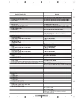
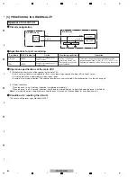
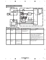
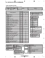
Specifications for port monitoring
Port Name
SD/PD Indication
Active
RST2
ASIC power
(M-DCDC)
Shutdown occurs when the
signal is "L."
for 5 sec after PSW1 is ON.
or
for 2 sec while the unit is
ON.
RST3
AC power
AC_OFF when the signal is
"H."
Monitoring conditions
• Panel screen ON
(RST4 = H and PSW1 = H)
• While awaiting restoration
of RST2 (RST2 = L)
Operation
Shutdown occurs immediately
Blue LED flashes 13 times
Excepting passive standby
If "RST3 = H" (AC_OFF) is detected under the
monitoring conditions, a power-off process starts.
Monitoring of the RST3 port is continued, while
monitoring of other ports is interrupted.
Communication is controlled only by the IF
microcomputer. The port outputs are set as specified.
If the signal at the RST3 port continues to be H after
30 mS of waiting, monitoring is continued.
If RST3 is L, a restoration process starts according to
the latest power-on/-off status.
RST4
MAIN power
(RELAY)
Shutdown occurs if the
signal is "L."
for 5 sec after RELAY2 is
ON.
or
for 2 sec while the unit is
ON or in Functional STB.
RELAY2 = ON (High)
Shutdown occurs immediately
Blue LED flashes 13 times
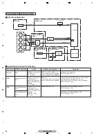
Power supply and DC-DC converter
SW_REG
MAIN
POWER
SW
DC/DC Converter
MODULE_Ucom
Inverter
AND
AND
RST4
RST3
PSW1
RST2
ACTIVE
AC shutdown
detection
Voltage
detection
Voltage
detection
DC_DC Converter
output control
PON/POFF
Command
Startup
Main ucom
Command
MAIN_UCOM
IF_UCOM
RELAY2
POWER SUPPLY Unit
DIGITAL ASSY
MAIN Assy
Circuit configuration
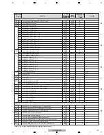
V+3_4V_D3
V+3_4V_D
V+3_4V_ACT
V+6.5V
AC_DET
RELAY1
V+12V
PULL_D
OR
PULL_U
V+3_4V_ACT2
V+6_5V
PULL_D
PULL_U
V+5_1V
PULL_D
PULL_U
Summary of Contents for ARP3476
Page 10: ...10 PDP 5020FD 1 2 3 4 A B C D E F 1 2 3 4 2 2 SPECIFICATIONS ...
Page 11: ...11 PDP 5020FD 5 6 7 8 5 6 7 8 A B C D E F ...
Page 12: ...12 PDP 5020FD 1 2 3 4 A B C D E F 1 2 3 4 2 3 PANEL FACILITIES Front Section ...
Page 13: ...13 PDP 5020FD 5 6 7 8 5 6 7 8 A B C D E F Rear Section ...
Page 14: ...14 PDP 5020FD 1 2 3 4 A B C D E F 1 2 3 4 Remote Control Unit ...
Page 15: ...15 PDP 5020FD 5 6 7 8 5 6 7 8 A B C D E F ...
Page 21: ...21 PDP 5020FD 5 6 7 8 5 6 7 8 A B C D E F ...
Page 22: ...22 PDP 5020FD 1 2 3 4 A B C D E F 1 2 3 4 4 BLOCK DIAGRAM 4 1 OVERALL WIRING DIAGRAM 1 2 ...
Page 25: ...25 PDP 5020FD 5 6 7 8 5 6 7 8 A B C D E F OVERALL DIAGRAM PDP 5020FD ...
Page 31: ...31 PDP 5020FD 5 6 7 8 5 6 7 8 A B C D E F ...
Page 71: ...71 PDP 5020FD 5 6 7 8 5 6 7 8 A B C D E F ...
Page 192: ...192 PDP 5020FD 1 2 3 4 A B C D E F 1 2 3 4 9 6 PANEL CHASSIS SECTION ...


