84
PDP-5020FD
1
2
3
4
A
B
C
D
E
F
1
2
3
4
[3] PROCESSING IN ABNORMALITY
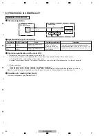
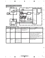
Specifications for port monitoring
Operation specifications of the main CPU
Conditions for resetting the circuits
Port Name
SD/PD Indication
Active
A_NG_B
AUDIO
Shutdown occurs when the signal is "L."
30 mS
∗
10 times
OTW
AUDIO
Shutdown occurs when the signal is "L."
120 mS
∗
3 times
Monitoring conditions
RST4 = "H" (always)
(Monitoring starts 2 sec
after the above conditions
are established.)
Operation
The main CPU operations described below will be
performed when either "A_NG_B = L" or "OTW = L" is
detected (established) under the monitoring conditions.
Speaker short-circuit
A_NG_B
A_NG_B
MAIN_UCOM
PULL_D
OTW
OTW
MAIN Assy
IO_AUDIO Assy
(1) Establish the short-circuit of the speaker by the main CPU
• After a warning indication is displayed for 5 sec, a shutdown is generated (the blue LED flashes 5 times).
• A warning indication is displayed for all input-signal types.
• Example of a warning indication: "The speaker terminals are short-circuited. After reconnection, turn the unit on again."
(2) Display conditions
When the panel is on: A warning indication is displayed immediately.
When the panel is off: A warning indication is not displayed immediately but is displayed when the panel is turned on.
Note:
A warning indication is displayed each time the panel is turned on if the conditions for a shutdown persist.
The circuits will be reset upon Standby ON/OFF.
IF_UCOM
DIGITAL
POWER
AMP IC
Circuit configuration
PULL_D
Summary of Contents for ARP3476
Page 10: ...10 PDP 5020FD 1 2 3 4 A B C D E F 1 2 3 4 2 2 SPECIFICATIONS ...
Page 11: ...11 PDP 5020FD 5 6 7 8 5 6 7 8 A B C D E F ...
Page 12: ...12 PDP 5020FD 1 2 3 4 A B C D E F 1 2 3 4 2 3 PANEL FACILITIES Front Section ...
Page 13: ...13 PDP 5020FD 5 6 7 8 5 6 7 8 A B C D E F Rear Section ...
Page 14: ...14 PDP 5020FD 1 2 3 4 A B C D E F 1 2 3 4 Remote Control Unit ...
Page 15: ...15 PDP 5020FD 5 6 7 8 5 6 7 8 A B C D E F ...
Page 21: ...21 PDP 5020FD 5 6 7 8 5 6 7 8 A B C D E F ...
Page 22: ...22 PDP 5020FD 1 2 3 4 A B C D E F 1 2 3 4 4 BLOCK DIAGRAM 4 1 OVERALL WIRING DIAGRAM 1 2 ...
Page 25: ...25 PDP 5020FD 5 6 7 8 5 6 7 8 A B C D E F OVERALL DIAGRAM PDP 5020FD ...
Page 31: ...31 PDP 5020FD 5 6 7 8 5 6 7 8 A B C D E F ...
Page 71: ...71 PDP 5020FD 5 6 7 8 5 6 7 8 A B C D E F ...
Page 192: ...192 PDP 5020FD 1 2 3 4 A B C D E F 1 2 3 4 9 6 PANEL CHASSIS SECTION ...


