


72
PDP-5020FD
1
2
3
4
A
B
C
D
E
F
1
2
3
4
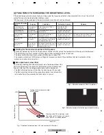
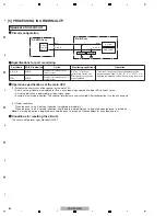
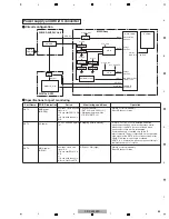
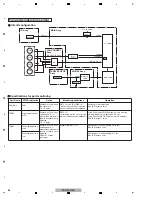
5.3 DIAGNOSIS OF PD (POWER-DOWN)
[1] BLOCK DIAGRAM OF THE POWER-DOWN SIGNAL
X DRIVE
ASSY
Y DRIVE
ASSY
SCAN ASSY
ADDRESS ASSY
(x8)
15VDD
Output
signal
VXKOFS1
VXKOFS2
15VDD
VNOFS
SCAN connector
disconnection
detection (upper)
SCAN connector
disconnection
detection (lower)
VKOFS1_2
VKOFS3
VKOFS4
IC5V
VH
VPRST
Resonance center
electric potential
Resonance center
electric potential
Y1
D22
D21
X1
D13
to
D20
AD1
OR
OR
OR
DCDC Convertor
Stop
PD detecdtion
Under voltage
detection
Under voltage
detection
Under voltage
detection
Under voltage
detection
Under voltage
detection
Under voltage
detection
Over or under
voltage detection
Over or under
voltage detection
Over or under
voltage detection
Over or under
voltage detection
Summary of Contents for ARP3476
Page 10: ...10 PDP 5020FD 1 2 3 4 A B C D E F 1 2 3 4 2 2 SPECIFICATIONS ...
Page 11: ...11 PDP 5020FD 5 6 7 8 5 6 7 8 A B C D E F ...
Page 12: ...12 PDP 5020FD 1 2 3 4 A B C D E F 1 2 3 4 2 3 PANEL FACILITIES Front Section ...
Page 13: ...13 PDP 5020FD 5 6 7 8 5 6 7 8 A B C D E F Rear Section ...
Page 14: ...14 PDP 5020FD 1 2 3 4 A B C D E F 1 2 3 4 Remote Control Unit ...
Page 15: ...15 PDP 5020FD 5 6 7 8 5 6 7 8 A B C D E F ...
Page 21: ...21 PDP 5020FD 5 6 7 8 5 6 7 8 A B C D E F ...
Page 22: ...22 PDP 5020FD 1 2 3 4 A B C D E F 1 2 3 4 4 BLOCK DIAGRAM 4 1 OVERALL WIRING DIAGRAM 1 2 ...
Page 25: ...25 PDP 5020FD 5 6 7 8 5 6 7 8 A B C D E F OVERALL DIAGRAM PDP 5020FD ...
Page 31: ...31 PDP 5020FD 5 6 7 8 5 6 7 8 A B C D E F ...
Page 71: ...71 PDP 5020FD 5 6 7 8 5 6 7 8 A B C D E F ...
Page 192: ...192 PDP 5020FD 1 2 3 4 A B C D E F 1 2 3 4 9 6 PANEL CHASSIS SECTION ...